Here is a schematic of a simple gauge.

In use, the sequence is:
Again, in practice, this may not be so easy. Today many drill presses don’t have a quill lock and/or the depth stop is not linear but circular, a lockable rotating collar on the feed handle arbor. You can hang a weight on the feed handle to simulate a lock but it’s almost impossible to get an accurate setting with a circular depth stop. Precise countersink depths depend on precise spindle control. Without it you’re pretty much back to trial and error.
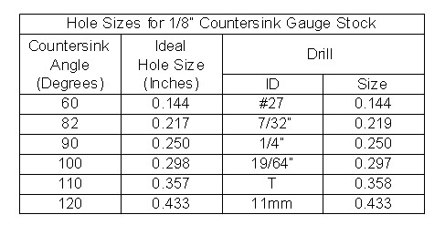
On a brighter note, the gauge is easy to make. Just drill a hole in a piece of CRS. I find 1/8” a good thickness because it lets me use commonly available drills for the holes. If you use uncommonly large or tiny countersinks, a different combination of thickness and hole diameter may be needed. If so, the formula at the end of the article defines the relationship.
Here is a table showing the hole sizes needed for the various countersink angles in 1/8” gauge stock.