Zero Adjustable Dials with Rotating Handles
for the Taig Lathe
by Keith Brooke
January 2007
Contents
Introduction
Design
Disassembly
The New Components
The Crank Arbor
The Arbor Lock Nut
Rotating Crank Handles
Taig Dial Modification
Final Assembly
Introduction
The stock Taig lathe leadscrew is driven by a hand crank with fixed micrometer dial and crank handle. While functional and cost-effective, this design can be improved significantly with modest effort. Precise tool movement is much more convenient with an independently rotating dial which can be adjusted to zero, or any other value, relative to the current position of the leadscrew. And it is much more comfortable to use a crank handle that rotates. This article describes how these features can be added to a Taig.
Design
There is nothing wrong with the quality of the Taig dial. It's just that, as both crank arbor and dial, it's not free to rotate independently. So it makes sense to simply provide a separate arbor on which it can rotate independently. On the other hand, it must not spin as if it were on ball bearings. It must be stiff enough to hold its setting as the leadscrew is turned but loose enough to be moved easily to a new setting. The answer is one used by Taig on its own milling machine. An ordinary snap ring is bent into a semi helix and rides in an elongated groove so as to exert a light spring pressure on the end of the dial. The damping effect is just about ideal. Finally, the stock handle is discarded and replaced by a new one which rotates on a separate axle screwed into the new crank arbor.
Disassembly
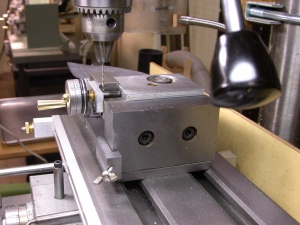
Photo 1: Drilling the Taig Leadscrew
Even if you are not planning to do these modifications, this section could be useful to you. Sooner or later, the leadscrew backlash will become excessive and need tightening up. Here's one safe way to get it apart.
Taig uses a little Loctite to secure the factory settings of the dial and it's not always easy to loosen it. The photos show how a hole drilled in the leadscrew allows a tommy bar to counter the force used while freeing up the locknut and dial. This is a #53 (.0595") hole which is just big enough for an .050 Allen key. This key offers some safety in that it will bend before you can put too much torque on the leadscrew.
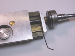
Photo 2: Using an Allen Key as a Tommy Bar
Once the Allen key is in place, the brass acorn lock-nut can be removed with a 5/16" socket. Then the dial can be unscrewed. Sometimes they come right off and sometimes heat is needed to soften the Loctite. A small butane torch works very well. In any event, if the key starts to bend, back off and apply a little more heat. Take it easy and it will ultimately come free.
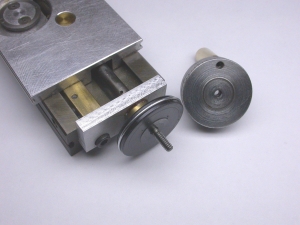
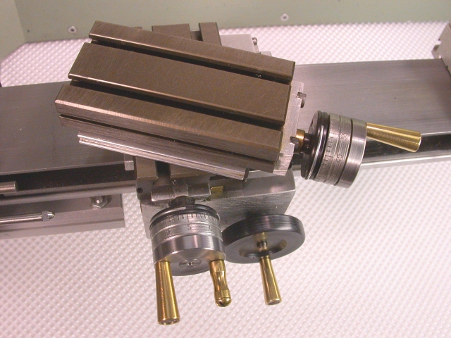
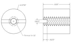
Photo 3: The Disassembled Taig Dial Assembly
Finally, here is what the disassembled dial assembly looks like. There is an unthreaded boss of about 1/10" and about 3/8" of 6-32 thread. The thread is not full depth all the way so that anything threaded onto the shaft will tend to tighten as it nears the boss. I assume that this is by design to help maintain the final backlash adjustment. The acorn nut provides additional security and a hint of elegance. In this case, the crank handle was replaced some time ago with a rotating one but in most cases the stock handle will have to be driven out with a pin punch to get the dial ready for later modification.
The New Components
Here is an exploded view of the new assembly and a description of the parts required.
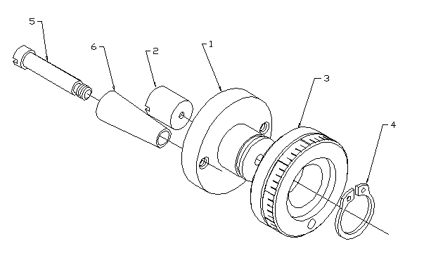
Parts List
| Part | Quantity | Description | Material |
|---|---|---|---|
| 1 | 1 | Crank Arbor | 11/16" length of 1 1/4" dia 12L14 rod |
| 2 | 1 | Crank Arbor Lock Nut | 1/2" length of 3/8" dia 12L14 rod |
| 3 | 1 | Modified Taig Dial | As Supplied |
| 4 | 1 | 9/16" External Snap Ring | As Supplied |
| 5 | 1 | Crank Handle Arbor | 1 1/4" length of 1/4" 12L14 rod |
| 6 | 1 | Crank Handle | 1" length of 3/8" Brass rod |
The Crank Arbor

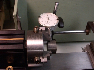
Photo 4: Indicating the Stock True
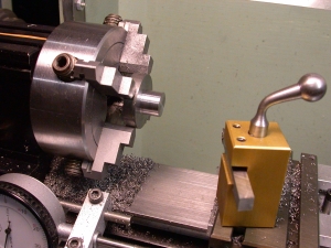
Photo 5: Turning the Crank Axle
Cut an 11/16" long piece of 1 1/4" diameter 12L14 steel. Dial indicate it true in the 4-jaw chuck leaving 1/2" exposed for machining. Face off the end and turn the axle part to 9/16" diameter for a length of .410 inches. This length is based on a Taig dial thickness of .404" and thus allows .006" for end play. Taig dials from different production runs may vary from this dimension so you should check yours and adjust if necessary.
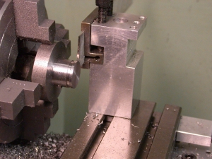
Photo 6: Turning the Circlip Groove
Turn the circlip groove 1/16" wide, .024" deep and .051" in from the end. A standard 9/16" snap ring is .039" thick so this gives an additional .024" or so for its spring action.
Lightly chamfer the end. Center drill, then right through with a #35 (.110") drill for the 6-32 thread. Counter bore the end #28 (.1405") about 1/10" deep.
This completes work on this end of the arbor. Wear is reduced on the tap by leaving the actual threading until after the nut recess is bored from the other side.
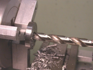
Photo 7: Drilling the Lock Nut Recess
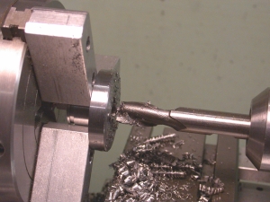
Photo 8: Boring the Bottom of the Lock Nut Recess
Reverse the arbor and hold it in the 3-jaw chuck by the 9/16" diameter section. Take enough off the 1 1/4" diameter to clean it up and face it off to 1/4" long. Chamfer the end to about the same as on the Taig dial. Drill 3/8" .410 deep and then bore the bottom flat with a 3/8" end mill.
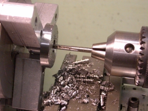
Photo 9: Tapping the Crank Arbor
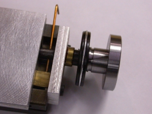
Photo 10: Testing the Crank Arbor Fit
Tap the spindle hole 6-32 and try the new arbor on for size. The only remaining job is to drill and tap the 8-32 crank handle mounting holes. Some people like two handles, others just one. Providing two holes now allows either configuration later.
The Arbor Lock Nut
This is just a matter of cleaning up a .410" length of 3/8" steel, then drilling and tapping it 6-32. Slotting can be done with a hack saw or with a 3/64" slitting saw.
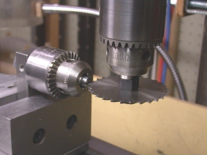
Photo 11: Slotting the Lock Nut
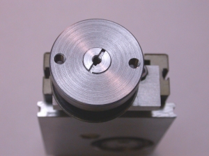
Photo 12: The Lock Nut Installed
Rotating Crank Handles
There is nothing special about these crank handles. The plans show a common design used in this particular instance. But the only requirement is the 8-32 thread. Otherwise, the shape and size are strictly a matter of personal preference.
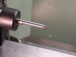
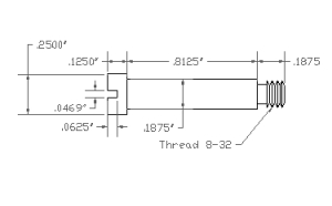
Photo 13: The Crank Handle Arbor
The stock is fed through the headstock and held by either a collet or the 3-jaw chuck. Starting with 1/2" or so projection, turn the .164 diameter for the 8-32 thread. Use a 1/16" parting tool to provide a groove next to the shoulder for the die to run into when threading. Move the stock farther out of the chuck to turn the 3/16" shaft. Finally, thread the end 8-32. A tailstock die holder works best but any way that gets the thread reasonably square is fine.
Set this part aside for the time being. Before it is parted off, it will be used as a headstock arbor to hold the handle while turning the taper.
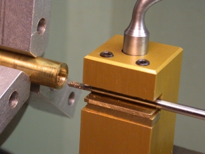
Photo 14: Boring the Handle
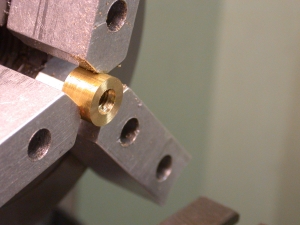
Photo 15: The Sacrificial Nut
Cut off a piece of 3/8" brass a little longer than needed for the handle. Face the end, then drill through 3/16". Counter bore the end 1/4" diameter, 1/8" deep for the head of the axle screw. A 1/8" HSS drill blank can easily be ground to make a great mini boring bar.
Cut off a piece of the same brass about 1/4" long. Face the end, drill it 3/16" diameter about 1/16" deep, then drill and tap 8-32. This is a sacrificial nut that will be used to hold the handle on the arbor while the taper is turned.
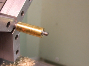
Photo 16: The Handle Installed on the Handle Arbor
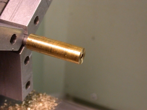
Photo 17: With the Sacrificial Nut Installed
Reverse the handle in the chuck and face off to a length that gives just a little end play when put on the arbor. Thread the sacrificial nut on the end and tighten it with pliers to hold the handle fairly tightly.
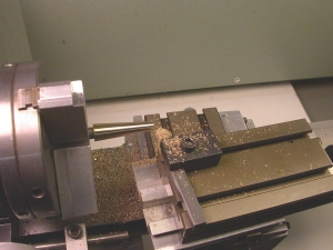
Photo 18: The Handle Taper Completed
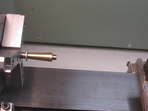
Photo 19: Handle Reversed for Butt Rounding
Mount the top slide and set it to the 4 degree taper angle. Turn the taper right through the sacrificial nut using light cuts of .005" or less and slow feed. Brass is pretty easy to turn but the holding power of this arbor setup is not very great.
Reverse the handle on the arbor and use a file to lightly round over its butt end.
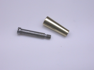
Photo 20: The Crank Handle Set
The last operation is to part off the arbor and slot the screw head. This completes the handle and arbor set which can now be attached to the crank arbor. A little light grease is probably not a bad idea.
Taig Dial Modification
Here's where we burn our bridges. Up until now, if things didn't work out just right the whole thing could be restored to stock with just the loss of a little time and material. Modifying the dial is a non-reversible commitment.
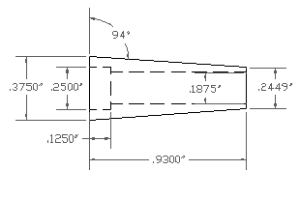
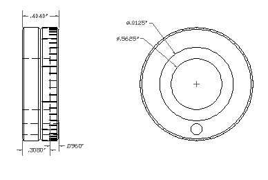
Here are the dimensions of the modified dial. As mentioned previously, these are based on a Taig dial that is .404" long and would have to be adjusted to suit a different size.
If the dial is to rotate nicely without any wobble, it must be bored perfectly normal to the end and concentric with the outside periphery. The main problem here is how best to hold it while this is done.
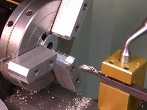
Photo 21: Soft Jaws Modified to Grip Taig Dial
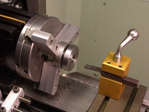
Photo 22: Testing the Dial Fit on the Crank Arbor
Reverse the soft jaws on the 3-jaw chuck. Grip a 1" washer right next to the chuck base and bore a recess in the jaws about 1/4" deep and to a diameter of about 1 1/8". Open out the jaws, remove the washer and grip the 1 1/4" Taig dial. This technique gives all the accuracy required for this operation. The jaws can later be reversed back to normal and nothing has been lost.
Chuck the dial with the micrometer graduations toward the tailstock. Drill it to 1/2" and bore out to 9/16"+ using the new arbor as a plug gauge to get a nice easy rotating fit.
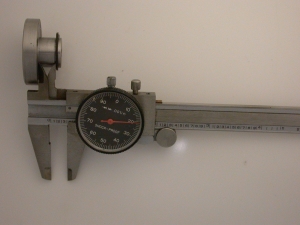
Photo 23: Checking for the Dial Bore Length
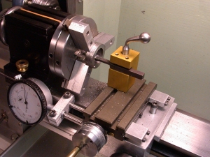
Photo 24: Boring the Circlip Recess
Measure the actual distance from the arbor shoulder to the snap ring inner face. The circlip recess in the dial should be bored to leave the bearing surface about .010-.015" less than this but still ending within the range of the circlip groove. In this case, the distance was .323". The final dial bore should be .323 - .015 = .308". The dial thickness of .404" less the .308" bore leaves .096" to be bored for the 13/16" diameter circlip recess.
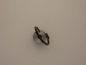
Photo 25: The Circlip Bent into a Semi Helix
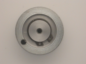
Photo 26: The Circlip Installed
If the dial is now put on the arbor and the snap ring put in its groove, the dial will just spin without much friction. But if the snap ring is first bent as shown to make a kind of spring, it will press on the dial and make its movement somewhat restrained. This is the intended effect.
Final Assembly
Lock the slide with the center gib screw, insert the Allen key tommy bar and tighten the crank arbor onto the leadscrew to give about .002"-.003" backlash as measured by the leadscrew dial. This is about what you find on the stock Taig assembly and seems to be near the limit that this leadscrew design can handle. Secure the setting with the lock nut and the job is complete. If you want to use a little Loctite, 222MS will allow easy adjustment later on without the need for heat.
© Copyright 2006,2007 Keith Brooke. Queries and comments welcome. Please put the words 'Taig Dials' in your e-mail subject to bypass my junk mail filter.
 This document produced with Evrsoft's 1st Page 2000 Version 2.0 Free Edition.
![]()