Cross-Slide Table Modifications
by Keith Brooke
October 2007
Contents
Change List
Dial Gauge Control for Table Movement
Table Locks
Thrust Bearing
Leadscrew and Nut
Dials and Handles
Table Stops
Appendix - Making the Lead Screw
Introduction
It seems to me that all drill presses should have the same kind of work holding and positioning features as a milling machine. Recently the availability of inexpensive Asian devices has made this capability much closer to affordable.
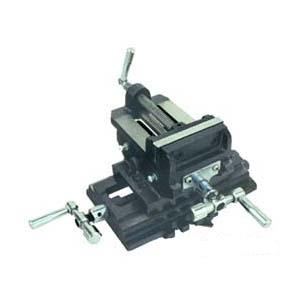
Photo 1: Popular X-Y Drill Press Vise
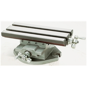
Photo 2: Popular Cross-Slide Drill Press Table
For several years I used a simple X-Y vise as shown in Photo1 because it was cheap and reasonably functional. The cross-slide table as in Photo 2 was available but was a couple of hundred dollars and didn't seem worth it at the time. Then a small sale and a big moment of weakness coincided and I made the switch. I bought mine at Busy Bee in Canada but everybody else's product looks pretty much the same.
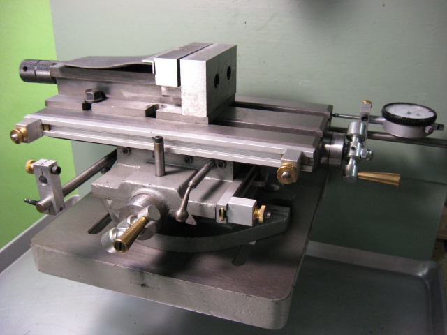
This table was usable as delivered but could never have been mistaken for a professional tool. I started nibbling away at its shortcomings and ended up with little of the original but the castings. Since it was done piecemeal, I wouldn't do everything exactly the same if I were doing it again as a unified project. But here's what I did and why for what it's worth.All modifications were done with a Taig lathe and a Rockwell drill press.
Change List
As far as I can recall, the following changes are listed in pretty much the sequence in which they were made.
The original gibs were steel and not suited to wearing in for that nice silky movement. I just made exact duplicates in brass. Over time they have improved the action noticably.
With the poor leadscrew dials it was just about impossible to move the table with any precision. Since I wanted to drill accurately located holes, this was important. I tried mounting dial gauges with magnetic bases and arms but found it surprisingly difficult to get them placed just right. Constant headache. So here's my solution.
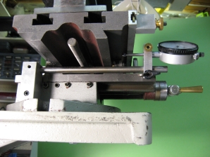
Photo 3: Y-axis Dial Gauge Arm
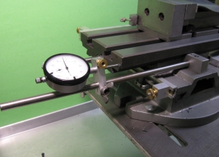
Photo 4: X-axis Dial Gauge Arm
Photos 3 and 4 show the mounting blocks and rods installed to hold dial gauges for measuring table movement in the X and Y directions. This eliminates any uncertainty because of backlash, loose gibs or a sloppy lead screw.
Locating the table precisely is not much help if it's going to jiggle around whenever the tool hits the work. So locks are needed to make sure it stays put.
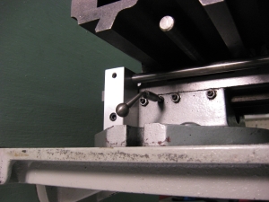
Photo 5: Y-axis Table Lock
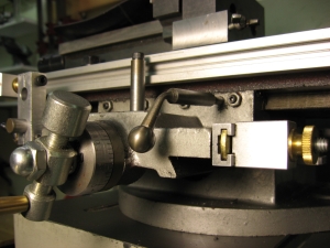
Photo 6: X-axis Table Lock
Photos 5 and 6 show the extra gib holes drilled and tapped to take the ball handled locking screws. Once tightened, these keep the positioned table perfectly stationary. Very accurately spaced holes can be achieved.
Thrust Bearing
I wanted to try light milling on the drill press since I didn't have a milling machine at the time. Experiments showed that there was just too much uncontrolled table vibration. For milling, the table should be as jiggle free under movement as when locked down. Once the gibs are properly adjusted, the only other component allowing uncontrolled motion is the lead screw. I started with the thrust bearing where I assumed (incorrectly) all the backlash to be.
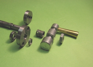
Photo 7: Original and New Thrust Bearings
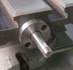
Photo 8: Mounted New Thrust Bearing
The original was just a steel disc with lots of non-adjustable backlash determined by how (not very) close to it the outer sleeve was pinned to the shaft during manufacture. The new one carries a ball bearing and spacer so the backlash is determined by the precision of the ball/race fit. If I were doing it again, I'd make this block thicker and mount two ball bearings with a spacer between and some bearing preload. It's amazing how much play there is in a single ball bearing. I never thought of this until later but couldn't have done it originally anyway because I was fitting it to the original leadscrew and was limited to the thickness of the original thrust plate.
The new plate had to be larger in diameter to make room for new mounting holes outside the bearing recess.Leadscrew and Nut
The new thrust bearing helped but didn't completely eliminate the problem. The table could still be moved perceptibly back and forth. So I took the whole thing apart to have a look at the leadscrew assembly.
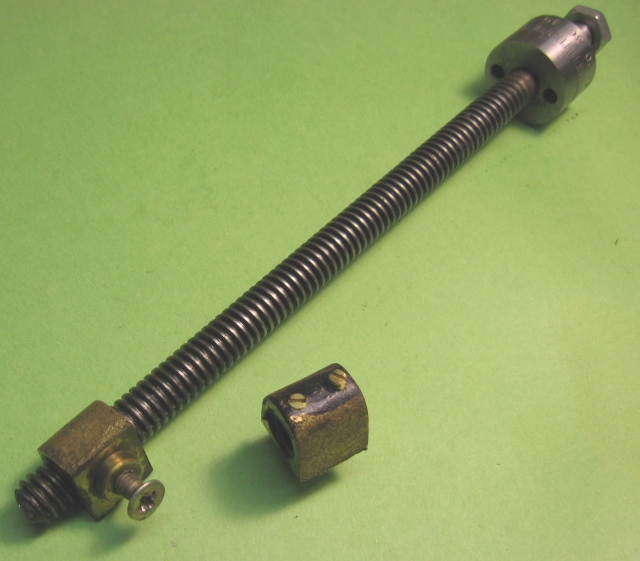
Photo 9: Original Leadscrew Assembly
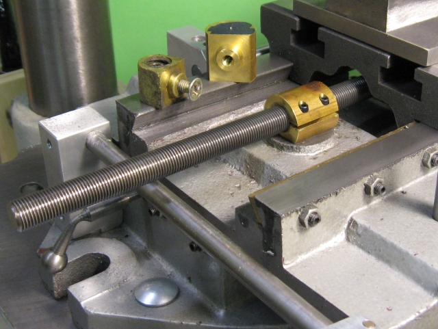
Photo 10: New Leadscrew and Nut Assembly
The new lead screw works like a charm and is as smooth as silk.While the thrust bearing could be improved, it's just not worth the trouble because the backlash is quite acceptable.
Dials and Handles
The original dials were intended for a 10 pitch leadscrew and were too small. The new ones have 50 divisions to suit a 20 pitch leadscrew and are the same size as the new thrust bearing carrier.
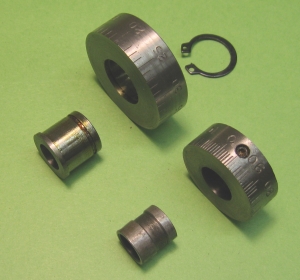
Photo 11: Original and New Dials
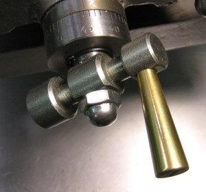
Photo 12: New Dial Mounted
The increase in leadscrew pitch means more turns per inch table travel so rotating handles ease the wear and tear on fingers.
Table Stops
Adjustable table stops make certain kinds of repetitive operations much more convenient.
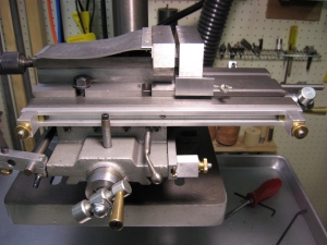
Photo 13: X-Axis Table Stops
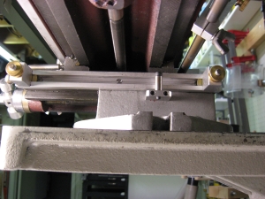
Photo 14: Y-Axis Table Stops
This section has nothing to do with changes to the cross slide table but adds the final axis control for drill press work and is included to complete the subject.
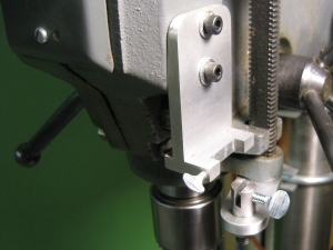
Photo 15: Mount for Dial Depth Gauge
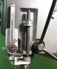
Photo 16: Mounted Dial Depth Gauge
Appendix - Making the Lead Screw
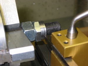
Photo 17: Making a Bearing for the Threaded Rod
The leadscrew is far too long to be held between centers on a
Taig. To give the steady rest something to ride on, lock two 1/2-20
nuts together on a short length of rod and turn half of one of them to
a nice round.
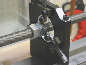
Photo 18: Rod Bearing as Tailstock Subtitute
Now cut a length of threaded rod about 1" longer than the lead
screw to be made. Grip it in the three-jaw and support the outboard end
with the just-made round riding in the steady rest, a kind of
substitute for a
tailstock dead center.
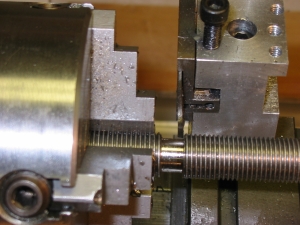
Photo 19: Turning a Starting Diameter
Use the parting tool to produce a sufficient length of the
required diameter so a regular left-hand tool can be used to continue.
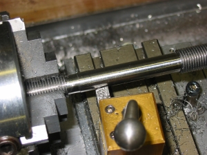
Photo 20: Completing the Major Diameter
A normal left-hand tool is used to complete the major diameter
for the thrust bearing, dial and handle.
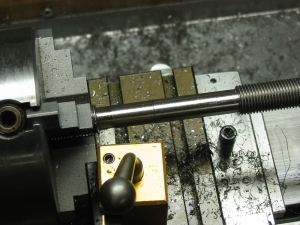
Photo 21: Turning the Thread Diameter
Turn the reduced major diameter for the thread being used. Cut
off the leadscrew to the required length.
Photo 22: Threading the Leadscrew
Mount the die holder in the headstock and lock a couple of 1/2-20 nuts on the other end for a hex socket ratchet. Run the thread. This completes the leadscrew.
© Copyright 2007 Keith Brooke. Queries and comments welcome. Please put the word 'Taig' in your e-mail subject to bypass my junk mail filter.
 This
document produced with Linspire's
Open Source Nvu Version 1.0
.
This
document produced with Linspire's
Open Source Nvu Version 1.0
.
![]()