Pictures of the Taig Lathe, Mill & Other Tools and
Accessories
Here are pictures of the Taig Micro Lathe and Taig Milling
Machine,
pictures of my machines and other Taig users machines, modifications
and projects.
I want pictures! Send me your Taig pictures and I will post them. Mods,
projects, even your machine just sitting on the bench.
Last Updated June 1st, 2017
Back to the
Taig page
Table of Contents
Sections with new additions in Bold type,
new pictures in Bold type.
This page can be a bit unwieldy, but you will find a lot of treasures
by poking around.
Use the "find" function of your browser to search for
particular words (usually ctrl + "f" keys, pressed together.)
For the latest pictures it's easier to
look at the My Taig Blog, which presents the
pictures in a much easier to read format.
- Tracy
Presnell's Taig CNC mill
making parts (February 15th, 2005)
- Mike
Rowe's CNC Taig Mill and
Paintgunsmithing (August 8th, 2001)
- Wayne
Field's Taig and Model
Wagons (October 3rd, 2001)
- Tom
Cumming's Extended Base
Lathe (May 28th, 2001)
- Geoff
Kingma's Lathe and Mill
(May 24th, 2005)
- Bob
Urso's Miniature Pistols,
Made on his Taig Lathe. (October 4th, 2005)
- Laurie
Keating's Taig Lathe and
Projects
- Ken
Jenkins' Taig Lathe
- Bob
Pinkus' Taig Lathe
- Robert
Sidor's Taig Lathe
- Randy
Gordon-Gilmore's Taig
Lathe Modifications
- Alex
Newman's Taig Lathe and
Indicator Mount (September 1st, 2007)
- Hideo
Kawa's Taig and
Accessories
- Andy
Moe's Modifications
(January 10th, 2003)
- Steve
Bachmann's Taig Projects
(January 24th, 2004)
- Keith
Shaw's Lathe and Mill
projects (April 6th, 2006)
- Dave
Gil's Taig of 20 years.
(June 10th, 2008)
- Mitch
Singler's Lathe (January
24th, 2004)
- Forrest
Atkinson's Taig
(January 26th, 2005)
- Barry
Boling's Accessories
(April 6th, 2004)
- Michael
Gamber's Taig CNC Mill
and Enclosure (January 31st, 2006)
- Mark
Jenk's Taig CNC Mill
Conversion (May 6th, 2004)
- Sylvain
Sauve's Taig Lathe
with Leadscrew Modification (July 25th, 2004)
- Gene
Martin's Quick Change
Gearbox, Back Gear Taig Lathe Modifications (August 30th,
2004)
- Terry
Taylor's Taig CNC Mill
and Projects (July 11th, 2006)
- Bob
Burandt's Gap Bed Taig
Lathe Modification (January 1st, 2005)
- Tom
Benedict's Taig Lathe
and Milling Machine (March 9th, 2005)
- Jim
Knighton's Taig Lathe (July
27th, 2005)
- Kelly
Shamash's Taig Lathe
(April 8th, 2005)
- Frankie
Flood's Taig Projects (April
29th, 2005)
- Gordon
Reithmeier's Projects.(May
24th, 2005)
- Harvey
Redmon's Taig Lathe
and Milling Machine Project (June 9th, 2005)
- Larry
Gitchell's Taig Milling
Machine Modifications (July 6th, 2005)
- Michael
Dhabolt's Taig Lathe
(July 27th, 2005)
- Des
Bromilow's Taig lathe
and indexing head (August 23rd, 2005)
- Paul
Chamberlain's CNC
mill enclosure (July 11th, 2006)
- Lynn
Livingston's Taig Mill
Motor Plate, Speed control, and other projects. (October 4th,
2005)
- Alan
Coppen's Taig Lathe
accessories, filing rest and other stuff. (January 4th, 2006)
- James
Tremel's Taig Mill
and Projects (January 4th, 2006)
- Richard
Crook's Taig
Lathe and Mill Modifications. (April 6th, 2006)
- Asi
Combelis Taig Mill and
Projects He's working on a flight simulator cockpit (April
28th, 2006)
- George
Weightman
has an excellent and unique radius turning tool on his lathe (April
28th, 2006)
- Greg
Miller does a
lot of modifications to his Taig mill. (May 18th, 2006)
- Larry
Snyder has
a compact shop and has modifed his mill and lathe.(July 11th, 2006)
- Bob
Swartzendruber's
Taig Lathe, Metal Pens and Pencils (September 1st, 2007)
- Russ
Hobgood's
Extended bed Taig Lathe and Mill Modifications. (March 10th, 2009)
- Ray
Ackley's Taig
Mill CNC Setup pictures (October 29th, 2006)
- Russell
Waters
Homebrew CNC Lathe with Taig Headstock (December 12th,
2006)
- Ed
Chesnut's
Taig Lathe and Plastic Injection Mold work. (January 26th, 2010)
- Christopher
Smith's
Taig Lathe (February 19th, 2007)
- Dean
Williams Taig Lathe
(June 12th, 2007)
- David
Jost's Taig Lathe
(July 24th, 2007)
- Jim
Silkey's Taig Milling
Machine Modifications (September 1st, 2007)
- Thomas
Burgin's Taig CNC
mill and Projects (August 8th, 2009)
- Edward
Slatt's Taig Mill
Projects (September 1st, 2007)
- Peter
Zicha's Modified Taig
Lathe (August 23rd, 2016)
- Lee
Nichols Cue Lathe
(December 30th, 2007)
- George
Plezia's CNC Mill
(August 6th, 2007)
- Stephen
Campbell's Projects
and CAD drawings (June 10th, 2008)
- Mark
Peterse Taig
(Grimberg) Lathe (April 22nd, 2008)
- Lou
Somers Taig
Lathe and home made accessories (January 26th, 2010)
- Rick
Voegelin's
Modified Taig Lathe and Accessories (April 22nd, 2008)
- Derrick
Kortvejesi's
Taig Lathe and Airgun-Smithing projects (April 2nd, 2009)
- Toni
Markus
(October 15th, 2008)
- Stephen
Ellacott (October
7th, 2009)
- Rick
Kernell
(January 7th, 2010)
- Lewis
Bishop (November
12th, 2009)
- Ron
Kiely (November
12th, 2009)
- Pete
Rees
(February 24th, 2010)
- Norman
Crowson
(March 15th, 2010)
- Bob
Eckstein (May
22nd,
2010)
- Gerald
Hynes
(April 20th, 2010)
- Leon
Dionne
(May 22nd, 2010)
- Havard Buhag
(January 10th, 2010)
- Monty Remon's Taig
Lathe (August 23rd, 2016)
- Guy Zattau's Taig
Lathe and Taig CNC Mill (January 10th, 2010)
- Steve Fornelius'
Taig Mill (March 3rd, 2011)
- Irv Bakeland's
Sherline Motor Adaptation to the Taig Mill (April 7th, 2011)
- Ed Maisey's Compound
Slide Modifications (June 14th, 2012)
- Eldon Johansen's
Mill Mods (April 21st, 2014)
- Pat Miller's
lathe modifications (April 21st, 2014)
- Christopher Smith's
lathe modifications (April 21st, 2014)
- Doug Jones's Taig Lathe (June 1st, 2017)
- Jose
Rodriguez's Taig Lathe and
Accessories
- Jose
Rodriguez's Harbor Freight
7x10 Minilathe and Accessories
- Jose
Rodriguez's Home Made
Milling Machine
- Jose
Rodriguez's Model Steam
Engines
- Nick's
9x20 Jet Lathe
Accessories (July 1st, 2001)
- Nick's
Drill Press, Bandsaw
Accessories, etc.
- Nick's
Shop (January
18th, 2003)
| Taig Lathe |
The L1017 Assembled Taig Lathe with
1150 tailstock, 1097D tool bit, 1023 mounting board, 1162 pulley set
and 1192 drill chuck |
|
|
Depth stop for workpiece in chuck |
|
|
4 jaw 3 1/4" dia. chuck 3/4-16 thd
mount jaws adjusted independently (reversable heat treated steel jaws) |
|
|
Lathe Dog, holds work piece while
turning between centers. |
|
|
Face plate 3 1/4" dia. 3/4-16 thd
mount |
|
|
Face plate angle bracket set |
|
|
Face plate, 2" dia. 3/4-16 thd mount |
|
|
4 inch swivel joint tool rest (wood
turners) |
|
|
Collet set, collet closer with 8
collet sizes 1/8,5/32,3/16,7/32,1/4,9/32,5/16 and one blank |
|
|
4 blank collets furnished unslotted
for making special arbors (may be bored and slotted) |
|
|
3 Jaw 3 1/4" dia. self centering
scroll chuck (steel body) with reversable aluminum soft jaws 3/4-16 thd. |
|
|
Additional blank soft jaw set for 3
jaw chuck |
|
|
Full circle soft jaw set for 3 jaw
chuck |
|
|
4 Jaw 3 1/4" dia. self centering
scroll chuck (steel body) with aluminum soft jaws 3/4-16 thd. |
|
|
1/16-3/8" Jacobs drill chuck,
commercial quality 3/8-24 thd. |
|
|
6 piece high speed steel tool bit
set, left,right,45 degree,round nose,boring bar, and cut off |
|
|
Slitting saw arbor, screws directly
on spindle including wrench |
| 1110ER |
Slitting saw arbor, 3/8 shanik for
ER16 3/8" collet |
|
|
.032 X 2 1/2" dia high speed
slitting saw |
|
|
Grinding wheel arbor, screws
directly on spindle |
|
|
Grinding wheel set |
|
|
Blank arbor 1.00" dia. screws
directly on spindle (may be machined for special jobs) |
|
|
Blank arbor |
|
|
Drill chuck arbor (3/8-24 thread),
attaches Jacobs chucks to headstock spindle |
|
|
Drilling tailstock, lever operated
5/8" off set with dead center, 3/8-24 thd for drill chucks |
|
|
Needle bearing center, spring loaded
(fits in tailstock) |
|
|
Die holder for tailstock (will
accept 13/16" and 1.00" button dies) |
|
|
Spare Gates polyurethane vee
belt(est. belt life 5000 hours) No.3M 315 12 1/2" flat length |
|
|
Spare Gates polyurethane vee
belt(est. belt life 5000 hours) No.3M 500 20" flat length |
|
|
Pulley set as above for 1/2" shaft
motor STD 3M 315 belt included (3M 500 belt optional) |
|
|
Extra tool post (same as supplied
with lathe) |
|
|
Back tool post, tool bit mounts
upside down, 2 tools may be used at same time |
|
|
T Bar Cut off Tool, height
adjustable (available 12/15/00) |
|
|
Steady rest 3/32" to 1 1/2" capacity |
|
|
Top slide (compound) mounts on
crosslide for cutting tapers and angles |
|
|
Radius Turner, swings Tool Bit in arc |
|
|
Milling attachment mounts directly
on crosslide (2 x 3 3/4" table) |
|
|
3/4-16 chuck adapter, adapts chuck
to mill table |
|
|
Fly Cutter, 1 1/4 to 2 1/2 inch
diameter, 3/4-16 thread mount, tool bit included. |
| 1224ER |
Fly Cutter, 3/8" shank for use in
the 3.8" ER16 collet, imported. |
|
|
Milling vice, 2.125" opening x 2"
wide |
|
|
Riser block kit for headstock and
tool post (provides 6.00 swing tailstock riser not incl) |
|
|
Tailstock riser only |
|
|
1" Spindle Wrench |
Taig CNC Mill
Pictures
Also see setup
articles here.
The Manual Mill in
Action
(most pictures of the older style manual mill)
- 2019
Taig Mill with 12" x-axis Travel
- The
dovetail plate that the headstock attaches to setup for vertical use.
- The
Mill with the headstock set horizontally
- The
dovetail plate setup for horizontal use.
- Taig
Mill, Milling 1/4" Aluminum Channel in One Pass with 1/4" End Mill.
- Taig
Mill, Flycutting Aluminum with 1-3/4" diameter Aftermarket Flycutter.
- Taig
Mill, Milling a 1/8" deep 1/4" wide slot in HRS, in one pass
- The
Finished Slot.
- Taig
and Sherline Mills Side by Side
- Taig
Mill, cutting 3/16" Wide Keyway in Taig Arbor
- 60
Tooth, 20 DP Gear Made on Taig Mill, with "Hob" Made on Taig Lathe and
Hardened, Mates with Taig Rack
- Taig
Mill, milling 1/2" wide, 3/16" deep slot in .050 passes, 304 Stainless
Steel (note: use copious quantities of coolant!)
- Electrical
enclosure of parts from Radio Shack
- Taig
mill with Taig Lathe riser block attached, so that 3/8" wide,
1/2" deep, 4.5" long slot can be milled in a 11"x8" Al plate.
- Gashing
teeth in gear (a replacement for a Delta drill press table raising
mechanism), using a Taig headstock as an index head.
- The
gear blank set up on the (Atlas 7") shaper, for finish forming the
teeth.
- Using
the 6" rotary table to mill radius on the end of 16" long Al bars
- #2
- #3
- #4
- setup
for horizontal work
- #2
Don't have time to make
clamps? You can buy a nice set, or
individual components, from LittleMachineShop.com
(see a review here)
Chris Hendricks sent me an
intruiging drawing for making a
little hovercraft out of a CD puck. I have to admit it need tweaking,
as the balloon tends to drag along the table, slowing it down, but it
does float on a cushion of air!. His drawing and puck can be found in
the owner
modification and projects section.
- Nick's
Taig
- Boring
Bar Holder
- Graduated
Carriage Handwheel and Spinner Handle
- Foredom
Handpiece Holder
- Knurling
Tool
- Indexing
Plate on Headstock
- Articulated
Indicator Mount on Headstock
- 6"
Travel Tailstock Ram & Lever Mounted in Tailstock
- Turning
14ga. SS Wire with Compound Slide, and Back toolpost Mounted Follower
Rest
- Typical
Work Done on Taig: Flanged Crown Pulley, Bronze Bushing, Knurled Lock
Knob, Bearing Housing with Internal Retaining Ring
- Accessories
Made from #1132 Blank Arbor, Clockwise from Top: 3/8" Mill Holder,
Headstock Tool Steel Center, Flycutter, Slitting Saw Arbor, 1/2" Mill
Holder, Boring Head and Albrecht Chuck Arbor, JT1
- Compound
Slide Lock Knob
- Knurling
Tool Holder
- Disassembled
Knurling Tool
- Index
Head made from Taig Headstock, Side View
- Index
Head, Back View of Mechanism
- .050
(.010 total removed) deep cut on blank arbor, notice the chip curling
off of tool.
- Altering
a Murayama String Trimmer (Weed Whacker) Spline Bushing to Accept a
Stihl Trimmer Head
- Tightening
live center against .016 3003H14 Aluminum Spinning Blank, using
homemade screw unit. The form is 1/2" thick mahogany screwed
to Sears 4" woodturning faceplate.
- Blank
halfway into spinning process. using polished 1/2 round
reground screwdriver as spinning tool, beeswax for lubricant.
- Trimming
spun form to completed shape with handheld parting tool.
- Two
spun halves of prototype birdfeeder parts I prototyped for a local
glass artisan.
- 'Emergency'
endmill sharpening using a 4" cup wheel, milling attachment and
homemade boring bar holder.
- Side
view, note Jacobs chuck used as handle for endmill, and depth stop.
- Using
back toolpost to turn shoulder on G scale model train wheel. Disc
mounted on blank arbor turned down to disc id.
- Drilling
six indexed holes in train wheel using shop made drilling block,
powered by a Makita cordless drill.
- A
home made stop for a grooving operation using the back toolpost.
- Another
view of the same setup.
- Carving
arbor/Speed lathe made from Taig headstock, I use this for buffing,
sanding on metal parts to spare the lathe, and for gemstone carving.
- How
a tap (held in a tap handle with a centering hole in the end) is used
on the Taig. The headstock is locked, and the tap turned by hand.
- Picture
of FROG x-axis CNC setup on carriage.
- Picture
of FROG spindle speed sensor mounted on adjustable arm 1/8" from magnet
affixed to index plate.
- Picture
of 1/4"-32 tpi thread cut with FROG threading mode on Taig - Look mom,
no leadscrew needed!
- Knurling
tool part laid out for drilling
- Drilling
first hole in stack
- Drilling
second hole
- Drilling
through two pieces to produce 5/16" radius
- Drilling
holes in the Steady Rest fingers to accept press fit bearing shafts.
- Slightly
fuzzy picture of some bearings I had laying around with shafts already
pressed into bores, I love my junk box!
- Bearings
installed in the steady rest.
- Making
a jacobs chuck arbor from an 1132 blank arbor. Step 1, drill a spanner
hole
- screw
arbor to spindle
- set
depth stop for threaded section length
- first
.050 deep cut taken
- blurry
picture of the 2nd .050 cut taken
- filed
end to nice radius and chamfered the end to ease the use of a die
- 3/8"-24
die in holder
- threading
with die holder, spindle stationary, die holder turning
- completed
thread
- chuck
mounted, with no runout (use a good chuck!)
Since I needed another hobby, here are some pictures of work on plastic
parts of a tank model
- Milling
the tubes in the model muffler to the same length
- Spot
drilling for tube extensions
- A
piece of plastic sprue turned to extent the muffler tubes
- A
clear piece of acrylic turned down for making a headlight
- Forming
the headlight dome with a form tool
- Parting
off the finished headlight
- The
finished headlights with the opaque plastic one they replace.
- A
PM models steam engine I made for my dad's birthday,
entirely made on the Taig lathe and mill.
- #2
- Radius
Turning Tool #1210 and home made setting tool
- Setting
Toolbit for correct radius with home made setting tool and feeler
gauges.
- Turning
radius on the end of 1/2" Aluminum rod (note projection from chuck face
- Woodturners
tool rest #1038 in action
- Flycutter
#1224 on the Taig mill
- Turning
between centers with Taig lathe dog #1034. Center is piece of
steel, held in 4 jaw chuck with 60 deg. center turned on it. Note use
of KENBO quick change tool holder.
- Cutoff
toolpost #1173 finished parting off 3/8" Al rod.
- A
holder for 1/4" screwdriver bits
- Drilling
the 3" x 5" UHMW block on the Taig CNC milling machine.
- My
father in law wanted a number plate for his mailbox. Roughly
3" x 6". The "0"s are slightly faceted because I screwed up the
polyline conversion. The 2 and 9 are smooth though!
- Filled
with several coats of black spraypaint, and the top sanded to
reveal the numbers.
- A
Neighbor needed a hex cut on an existing steel part that was
an odd diameter. This is how I held the part on the Taig mill using a
5C Hex Block, 1140ER drill chuck arbor, 1/2 drill chuck and my
toolmakers screwless vise. I think it came out quite well...
- #2
- #3
- Etsy.com
and Craft Magazine ran a contest to use the Craft logo. This
is the bracelet I entered.
- Another
view
- Another
view
- On
my wrist
- CNC
Milling the reverse of the logo into a piece of steel
- Rolling
silver against the steel "die"
- Rolled
link
- Punching
the holes with a Heinrich press
- Finished
links
- A
key fob/ring made out of 3/16" thick brass, milled directly
on the Taig CNC, for the same contest.
- Another
view
And no, I didn't win...
- Taig
has changed the Lathe cross slide leadscrew design. It allows
for slightly greater travel and is smoother.
- Disassembled
Note that the entire assembly is backwards compatible with older
lathes, but the screw alone is not. They only supply these new screws.
When people send me a few
pictures this is where they end up.
I generally edit the picture for size, play with brightness etc. I tend
to put new pictures at the bottom of this section, and put the
description in bold text until the next update. I
really appreciate pictures, and always welcome new ones, of any Taig
lathe, mill, or projects done on the machines. Feel free to email me
pictures in .jpg format, or mail a CD or regular photographs so I can
scan them. If you send me enough, I'll give you your own section on
this page.
- Sharon
Marshall's Taig , Notice jackshaft for greater speed control,
and the indicator holder made of pipe-fittings.
- Alan
Pinkus' Taig setup
- Detail
of Alan Pinkus' motor mount.
- Don Shaw made this nice bushing with his Taig to
allow him to use an electronic gyro on his r/c helicopter tail rotor
- Jyurki Vuorinen shows
what happened to his lathe in Los
Alamos N.M., this summer: His Spindle, His Lathe Bed.
(Don't worry, I sold him another one at cost before he went back to
Finland)
- Captain AJ made his own boring bar holder.
- Richie
Richardson Milling a Casting on His New Taig Mill
- Another
View
- Tom
Roach Modified his Old Craftsman (AA) Lathe to Take a Taig Crosslide
and 4 Jaw Chuck
- Closeup
of Crosslide
- Bruce
Bender has an old shortbed Taig
- Another
view, note gearhead motor driving lathe
- A
view of the foot at the end of the lathe and the old style tailstock
- Martin
Field's Maserati Chassis in 1/12th scale, Machined with the
Taig Lathe.
- Another
View of the Chassis, Notice gear selector in lower right
corner!
- Bob
Fritch has his steam engine running!
- A
Static View
- The
engine made on his Taig lathe
- His
version of the Boring Tool Holder
- Jack
Sadler's Bow Frog, partially completed
- Slide
and Ferrule of the Frog
- Bottom
of the Frog
- Finished
Frog
- Entire
Bow
- Jerry
Biehler's 7x10 lathe with Taig milling attachment mounted.
- Neil
Kempka Uses his Taig CNC Mill to machine plastic components for his
business, Integrity Instruments. #1
- #2
- #3
- #4
- Don
Mock's Boring Bar Holder # 1132 Arbor mounted to milling attachment by
# 1221 chuck adapter. Arbor also serves as 3/8 end mill holder.
- Quick
change Extension lever for tailstock. Adapter block was ready made -
direct from junkbox
- Detail
of adapter block - simple channel milled width of tailstock lever
- Clamp
from mill adapter use to prevent slipping of compound. A spare tool
holder or #1036 face plate angle bracket could be used.
- David
Goodfellow made these scotch rods on his CNC mill.
- Here's
David Goodfellows cribbage board and several stages of construction on
the Taig CNC mill. If I have time I'm going to redo the brass
pocket cover. I took too deep cuts on the lips, and the mill stalled on
the last pass; ended up finishing by hand. I was taking 0.005" per cut.
When I get a new piece of brass I'll do it at 0.003". The pegs (6 round
and 6 hex 1/4" brass) and the aluminum knob were done on the 7x10
minilathe from Harbor Freight. The 3-1/2" x 12" board is oak, stained
with Minwax Golden Pecan and finished with 3 coats of polyurethane All
in all, the project turned out rather well; the pics don't do it
justice. The cover is engraved with my daughter's and her fiance's
names, and "01 02 02," the date of their upcoming wedding.
- #2
- #3
- #4
- #5
- Alex
Strecker's portable rolling lathe workshop
- Dremel
Flexshaft holder for the lathe
- Knurling
Tool
- "Make-do"
Mill
- Alex
Strecker "I made this on the taig lathe and it works rather well" Index
Head
- #2
- #3
- Tap
handle
- Nut
of the tap handle
- Homebuilt
Mill "the Taig was very helpful for me."
- Homebuilt
Mill with dremel attached
- Bob
Wilkins amazing tailstock modification
Description: Ram - # 0 Morse taper, 1/4-20 LH lead screw, Self ejecting
for Sherline length tooling. Two quarter turn locking handles, one for
lathe bed locking, one for the tailstock ram. A standard type of
tailstock stepover arrangement for close adjustments
- View
#2
- View
#3
- Mike
Rosing sent a couple of views of his robot: "which I used
the lathe for but didn't have the mill" and a simple box "which I made
with help of the mill". "The robot axels were made on the lathe, and
the main turning pin for the front wheel was turned down so the end was
broad to hold it on. It turns very nicely, and there's no way I could
have done anything like it without the lathe. "
- #2
- The
box is for the outlet of a vacuum pump which I dragged out of
a trash dump. The pump itself is 40+ years old but in very good shape.
I used the mill to make the ends of some aluminum bars nice and smooth
and bolted them on to the pully drive. When I first tried the motor,
the pully got really hot. But with the aluminum on there, the heat
doesn't even get warm to the touch after hours of running. The brass
box was soldered, and I got the sides accurate to within a thousandth
using the mill.
- #4
- I
wanted to share a picture of what I consider amazing - I
used the Taig endmill to drill 127 .012" holes in a hex grid, and by
eye it looks pretty damn exact. I used two Grizzly dial gauges, which
are low cost but pretty nice. The most important thing was the smooth
sides on the Taig mill bed. Without that, the dial gauges wouldn't have
meant much. The people are Grizzly are pretty nice too, good follow up
on my order! The holes are all .069" apart. I suspect it's better than
.001" accurate too. I think it's pretty damn amazing!
- The
stuff I drilled is PETG, a food grade plastic. It has a
protective layer on both sides, and the large bubbles on some holes are
the protective layer pealing up from chips. Way easier than copper! My
wife helped me with the camera, it really is pretty amazing to get that
close and be in focus. Overall size is .720 flat to flat or .828 point
to point (inside to outside diameter)
- Pat
Sweeney used Taig parts on his homebuilt milling machine
- Tom
Welch mounted a Sherline DC motor on his Taig
I used a Sherline pulley by putting a blank arbor on the Taig and
turning the end down to 5/8, then I reversed the headstock and put the
Taig pulley on the arbor. Then I turned the Taig spindle down to take
the Sherline pulley. That worked great. I got the longest Sherline type
belt from the local sewing machine place, so I could mount the motor
back farther to give room for some index plates I am mounting on the
pulley.
- His
Index plate
- Detent
for the plate
- Another
view of the Detent
- John
Jones first small engines made on the Taig Cylinders are
brass tubing soldered to sheet brass bases. Crank supports are aluminum
sheet or angle. Crankshafts, pistons and flywheels are turned from
brass, steel or cast 63/47 solder. Connecting rods are piano wire with
turned and press fitted crank ends.
- #2
his favorite
- #3
from a kit
- #4
- Chris
Hendricks has come up with an interesting project, the "Crinz Puck"
I added pictures
of my attempts at making
this.
- His
puck, a small steam engine and a head transplant quarter
- View
#2
- View
#3
- Fred
Burton using a dog to prevent rotation of a brass workpiece held in the
3 jaw chuck, for threading with a die.
- Bob
Hurd made this box using his Taig lathe, The sewing box is
made of cherry, walnut, ebony, matapone, ivory, and ultrasuede for the
pin cusions on the top of the leg turnings. The drawer knobs are turned
ivory with ebony inserts
- Susan
Parker mounted her Taig Mill quite nicely. "Points to note. I
have mounted on a thick aluminium plate. I am using a Proxxon
Mill/Drill unit to drive the spindle. I works, but is under powered in
this application and will cut out from overheating if used for long. "
- Susan
worked more on her mill, "the motor is from Peatol. It isn't
quite as big as it looks as it has a fan and shroud - hopefully won't
suffer the overheating problems of the Proxxon unit. Spec: ELVEN Italy
(probably a badged Chinese import) type EB-63B4-B3, 0.18KW, 0.25HP
220Vac 50Hz, 1.67A, 1500 rpm."
- Brett
Flemming has mounted his Taig in a toolbox. "Here's a look at
how my "machine shop in a box" is coming along. I used a surplus center
treadmill motor, machined a pulley groove in the shaft, and used their
$45 or so dc controller. It runs smooth at 30 rpm, and will go to 3000
rpm. You cannot stop the chuck at 30 rpm, if the belt didn't slip, it
would wreck your hand!, It plows steel off like crazy, rigid taps (and
reverses thanks to a double pole single throw switch) . runs smooth and
is kind of fun to run. I mounted motor and controller underneath. How
about that, an underneath drive taig. Oh, and notice the 15000 rpm
grinder that runs when you hook up the dangling belt.....for sharpening
bits in the field.
- Colin
Heath made his version of the Crinz CD puck, out of plastic,
which really should work better than aluminum.
- Here
is his "bearing journal for my first stirling engine."
- Here
is the spark gap for his high voltage Tesla coil
- Wow!
That is fun with lightning.
- Phil
Warden says: I just completed a tread mill conversion on my
mill and am just so enthused that I had to write you. I milled a 1/4"
steel plate similar to the stock taig motor mount and I used a stock
taig pulley and belt system. I had to bore the pulley to fit the motor
but everything went real smooth. The mill now is load sensing and
variable speed with power to spare, what a difference! It's like having
a new mill.
- Face
milling some 7075 fortal aluminum. I am taking .015 passes
with the spillage face mill and could go deeper with no trouble. I must
also say the spillage face mill is well worth the investment, just a
outstanding tool for the taig mill.
- Jim
Crumley sent this picture of his Taig set up.
- Tony
Crowe mounted a TOS brand 4 jaw self centering chuck on his Taig.
I made the back plate by:
- Turning down some
stock all to diameter of the chuck.
- Faced the back and
turned a shoulder drilled and tapped
3/4-16.
- Turned it around in
the lathe and faced and made the
register turned it about 50 thou over size.
- Screwed the back
plate onto the taig lathe skimmed the
register some where near the size for location.
- Then i warmed the
chuck up in the oven turned the
register so it was a nice tight fit.
- Let the chuck cool
down i screwed grub screw backwards
into the chuck to mark the back plate where the holes go drilled them
and it all went back together it only has 1 thou run out with a 1/2
inch silver steel with a dti
- A
back view
- A
Sandvik 1/4 lathe tool
- Jim
Beggerow sent pictures "...of the modification to the Z axis
on my Taig mill. I used a 1/2 - 10 LH Supernut to eliminate backlash.
The reason is I use 5/16 & 3/8 end mills and do a lot of plunge
cutting, this eliminates the chatter during the cut. As soon as I can
take the machine out of service the next modification will be X
& Y axis with 3/8 - 10 supernuts. I also have a Homier lathe
converted to 3 axis cnc using a microproto controller and supercam.
- #2
- #3
- #4
- #5
- #6
- Modification
of my spare taig to a horizontal mill. Thought you might want
to see the pictures. Will test it next week.
- Kenny
Smith says: "I wanted to send a few pics of my lathe I got
from you a couple years ago. It sports one of your index kits on it. I
made the tailstock knobs, inspired by Tom Benedict, with the index kit.
Tom e mailed an idea and I made a set. The motor mount is a little
different also. The platform on the top keeps the angles below at a 90.
I have enjoyed my lathe so much. It has been the best thing I have
bought in years. "
- Tailstock
- Motor
and Mount
- Mark
Thomas has modified his lathe, here is his latest quick
change toolpost. "The lathe is fully CNC capable. The Index plate and
magnet are due for replacement as I'm changing to an optical sensor,
the electronics are done, just need to re-work the plate. The chip
wiper is a cut down cleaning brush, and I'm going to add one on the
other side as well, they work very well at keeping the lead screw
clean. The motor is 1/4 horse DC variable speed. "
- Closeup
of toolpost top
- Another
interesting view. Look at all the modifications he has made!
- An
overall shot of the lathe. The large extension on the
tailstock arm is nicknamed Ichiro. I haven't gotten around to painting
the bench yet hence all the spots of filler.
- An
example of the tool holders I've made so far for the QC toolpost.
The advantage is that they are very quick and easy to make. The blanks
take about 20 minutes each all CNC, and then the remainder varies with
the complexity of the finished holder. No need for special setups for
parting or boring anymore. One of the other advantages is that each
tool can be set the same depth on the Z axis, which greatly speeds up
CNC runs. In the works now are a knurling setup and ball cutter.
- A
shot of the mill and cabinet built to keep the chips inside
(used a couple of sheets of 5/8 plywood and a bit of solid wood). The
computer is running turbocnc and although the screen is small it's
perfect for monitoring progress. I use a different machine for my CAD
work and gcode editing except for minor code adjustments.
- Another
view of the mill There's a removable whiteboard of the left
door, and the ever convenient calculator on the right. The black box on
the lower left is the variable speed control. The controller at the top
right is currently based on Dan Mauch's 2amp chopper kits (one 3 axis
plus one 4th axis), I've added limit/home switch logic, tachometer (not
implemented on the mill itself yet), flow and mist control, as well as
spindle on/off. The case is oversize to allow future expansion to
Gecko's if necessary.
- A
shot of the forward control shift arm for my Roadstar 1600.
The original one is at the top, and it's fairly evident as to why I
needed a replacement. Material is 6061 aluminum.
- Jim
Shaulis made this great quick change toolpost
- Jim
sent me some more pictures of his toolposts: I just thought I
would send you a couple of pictures and a breif discription of my new
tool post. The last one I made you posted on your site, I would be
honored if you would do the same for me again as it trully graces the
mighty taig. You would be interested to know that most of it was
produced on the taig lathe, with exception to the mill work. Here is a
breif discription: The tool post main body and tool holders are made of
6061 aluminum, then they are powder coated with black chrome poly
powder making the set oil, solvent, acid, and UV protected. The coating
is impact proof to 165 LB per square in. The center 10/32 stud is
stainless steel and so are the height adjustment studs on the holders.
Both of the locking handles are oil hardened drill rod. The main body
center within the accentric cut locking mech. is 4046 aluminum and it
handles the pressure from locking the post to the common table. The
post main body is 1 1/2 x 1 1/2 including the dove tails, the tool
holders are 1" sq. x 1 1/2 long. The parting tool is made longer for
more stability and a positive 3 degree down sweep for the locking hood
insures no slip cut offs. The tommy bar makes it truly a mini big boy
toy. The boring bar is drilled and bored to .501 with a 1/4" of meat
around it. The tool holders will hold up to 3/8" cutters.The main body
height is 1 7/8" insuring that special cutters ground by you can be
easily put on center. As for its ability to handle a load, the original
prototype produced five sets, exact copys to the thousanth. Thanks and
dont let the chips get cold under your feet!!! Jim Shaulis
- That's
a lot of toolposts!
- Taking
a cut
- parting
(notice all the indicators)
- boring
- turning
- Nicolas
Juliano made these two Morse Code keys with his Taig lathe:
"I had purchased a lathe over a month ago, and I finally came up with a
project that I made exclusively with the Taig lathe. I made two single
paddle Morse code keys. However I did of course purchase the screws and
ball bearings. I have included some pictures. in case you are wondering
the larger Morse code key is set on a large 2 pound bronze casting,
that was intended to be a sheave. ( the smaller one is a prototype) I
just wanted to say, I am very pleased with my Taig lathe. "
- #2
- John
Stevenson modified a Taig manual mill into a CNC mill, with great skill
and precision They are the best motor mounts I have ever
seen!
- #2
- #3
- #4
- #5
- #6
- #7
- His
4th axis made from a gearbox.
- Just
been playing today with one of those digital dials you see on
the cheap import lathes. Wanted to see how easy they are to fit to a
Taig mill. They need a 20 tpi screw to work correctly which is why I
thought of the Taig. Mod is straight forward. You need to turn 5/8" off
the screw thread and also extend the small handle diameter by the same
amount. In other words you need an extra 5/8" to stick thru. The
mounting plate needs to be bored and threaded to fit the motor mount
and you need a spacer to go from the small diameter up to 10mm for the
inner sleeve to lock onto. X and Y are the same. Not done Z yet but
this is harder as it needs to go on backwards so the numbers aren't
upside down.
- Tom
Mix sent these pictures of his shop with Taig Mill
- #2
- #3
- Spent
the weekend working on the Taig mill. I had two old DC motors
I found at a garage sale 7 or 8 years ago, you know the kind of stuff
you just have to have. I think I paid $1 each for them at the time,
they had gear reduction on them 100:1. I ordered some small chain and
gears from Electronic Gold Mine (a site I got off your web site). Built
some bushings and motor mounts, a little electrical wiring from Radio
Shack and presto two axis of the mill are now powered. Very cool, saves
me from turning those little handles a couple of million times. :-)
- Detail
of powerfeed
- #2
- The
power supply I was using to run the DC motors for the axis
drives on the mill is my Lab unit, very expensive unit. So I decided to
build a new power supply just for the motors. I
found a cool web site where I could down load information on
building a 0-24 volt DC power
supply. Went to Radio Shack and bought all the parts and in one
afternoon, built the supply unit. It works very well. Included some
pictures. On a scale off 1-10 it was about a 5 to do. This rounds out
the project and cost about $45.00 to build.
- #2
- #3
- Voi
Nguyen's CNC mill conversion
- He
installed digital scales on his mill
- #2
- And
a neat spindle lock
- Another
view of his mill
- Michael
Sobik made this motor mount and base for his new Taig
- Note
his workbench doubles as the kitchen stove!
- David
Copley Makes beautiful flutes with his Taig Mill: I have
attached some photos of my set-up for machining the key mounting blocks
and holes on an african blackwood flute, as well as a picture of the
finished product.
- Sherline
Tailstock modified for use on the Taig mill
- Boring
a hole
- The
finished flute.
- His
Taig Mill Setup
- Milling
the wood tube.
- Drilling
a hole
- Boring
a hole
- View
showing sherline rotary table
- Notice
4 jaw chuck on rotary table
- More
milling
- Even
More...
- Chet
Culham made these great rings on his Taig. "I'm a jeweller in
Toronto and I do most of my work on a Taig lathe"
- #2
- A
necklace by Chet
- Another
cool ring
- Some
precise cufflinks
- James
Stevens does parts like this with the mill "The small
rectangular piece was machined for a connector. The fixture was for
PCB's"
- #2
- #3
- #4
- Sheldon
Stokes did a great job mounting his lathe
- The
drawer is convenient
- Tei
Newman made this turbine compressor diffuser mockup out of
plexiglass to test his program
- #2
- John
Bentley came up with a clever way of making an indexing pin
for his lathe index plate
- #2
The pin
- #3
(Drawing)
- Mark
Murray's home brew CNC Taig mill
- His
Spindle Motor
- X
Axis Servo Motor and Mount
- Y
Axis Servo Motor and Mount
- The
Mill Enclosure
- The
Coolant System
- The
CNC Controller
- John
Miller says: I very much enjoy reading your web site on the
Taig lathe. I have owned a Taig lathe myself for a number of years and
so did my father back in England (sadly passed away). For many years my
father has made modifications and attachments for both his and my lathe
and I would like to share these innovations with others if you think
them worthy. The very first modification that he made was to the tail
stock for drilling operations. As supplied, the short leaver is hard to
use except for very small drilling jobs. I have noted that many others
simply extend the length of the leaver. My fathers approach was to add
a threaded knob and feed screw. This approach allows fine control in
advancing the drill into the work but does not negate the original
quick leaver action when the control knob is fully retracted, since it
is the knob that is threaded not the brass bush attached to the leaver
arm. In addition, drill snatch that can occur when enlarging holes, can
be minimized by tightening the tailstock shaft clamping screw. This
modification requires that only one hole be drilled in the tailstock
leaver.
- Anthony
Musco made this adapter to use the Taig collets on his Unimat
lathe out of the 1221 spindle adapter
- David
Robertson cuts clock wheels on his Taig Mill. : I have a Taig
lathe, a Taig Mill and an extra head stock that I use for an indexing
fixture with the mill. This way I can use the same work holders among
the three devices. I make the dividing plate by using a 4" rotary table
on my Taig mill. Then I firmly attach the dividing plate to the
non-threaded end of the extra head stock with a bolt held against the
ID of the arbor with an expanding mandrel. I have a spring loaded arm
that holds a pin in the dividing plate at each of its positions. I
mount the fly cutter (which is flat) in a holder made from a Taig blank
arbor (and for pinions...) I have a fly cutter made from round stock
whose holder fits in a 1/4 in collet.
- #2
- #3
- #4
- #5
- Ted
Walls made his own CNC control for the Taig Mill: I started
building my Taig CNC mill about 9 months ago. Some years ago I built
the Camtronics 2A controller and converted my Sherline mill to CNC.
Having recently become interested in gauge 1 live steam loco's, and
finding the limited capacity of the Sherline frustrating, I decided to
put together a Taig CNC mill. When I converted the Sherline I built a
camtronics 2A controller, but after some discussion via email and the
yahoo group I did not consider this would not be able to efficiently
drive the Taig. Trying to think ahead, and allow for some upgrading in
the future, (possibly to a larger machine) I considered using Gecko
drives. Only wanting to build the controller once I decided, 1.
incorporate a 4th axis 2. have easily selected current outputs for the
range provided by the Gecko's 3. incorporate a spindle tacho. 4.
provide a probe input. 5. provide relay control for spindle and coolant
6.incorporate power supply for the motors, logic, and cooling fans in
the housing. 7.provide inputs for limit switches. Putting together the
controller meant providing a power supply to provide the voltage for
the motors, the logic for the Gecko's and power for a cooling fan. I
decided on a large toriodal (1000VA) for the motor power and a smaller
12V for the logic and fan. A small PCB was drawn up using Eagle to
provide a regulated 5V and 12V supply for the logic and fan supply. The
main motor supply being rectified by a large bridge rectifier and
capacitors. The tacho was built some time ago from a Camtronics kit.
This was disassembled ready to build into the housing. The relay and
limit switch PCB was drawn up using Eagle. This allows for 2 12V relays
and provides the pull-ups for the limit switches. The switches
themselves are yet to be installed. The PCB's were too large to be
milled out on the Sherline as it was, so I made an extended bed to give
me more movement in the Y axis. The controller was assembled and tested
on a baseboard and the cabinet duly made
- #2
- #3
- One
of the boards being milled on the Sherline mill using a Dremel.
The extended bed can be seen in the photo
- Having built the
controller, converted the mill and tested
it, I have used it since to produce parts for my gauge one Dee loco,
which is now nearing completion. It has also beeen used for milling
PCB's and engraving sing the Dremel. For normal milling I have mounted
the Sherline motor and controller. A recent article in The Model
Engineer pointed me to a material supplied for glueing wood veneers.
This is a thin (nomial 0.003") thermoplastic glue trade name gluefilm.
The material melts at about 100 deg C and forms a very strong bond
between 2 surfaces. I purchased some to hold 1mm brass sheet to a
baseboard whilst milling out the various panels for te superstructure
of my loco. Photo shows the splashers and cab sides being milled. The
brass sheet is glued to a piece of 1/8" aluminium which acts as a base.
- The
milled blanks, attached to the baseboard, being heated up to
soften the glue to allow them to be removed.
- The
finished items with the baseplate in the rear. The toolpath
can be clearly seen on the baseplate.
- The
nearly completed locomotive, gauge one Dee loco at its current stage of
completion
- Jim
Rich is using his Taig CNC mill to make parts for pneumatic G-scale
track switches
- Milling
the parts from brass
- closeup
showing air nozzle
- finished
mounting bracket after being bent 90 deg.
- Randall
Busbee's Cue Lathe
- #2
- Ed
Kline's Lathe: I recently acquired a box of parts at a
swapmeet that were parts of a Taig mill and a Taig lathe. After looking
at them carefully and looking at all the information on your site I
started to put the two together to make frankenlathe. This is a work in
progress as you can see from the attached images. I've machined the
head stock to take 5-C collets because of their availability and
versatility and fine detail work that I do with my projects. There
really is part of a Taig lathe and mill in there. I think you can spot
them! :) So far it seems to work very smoothly and accurately (check
out Ed's very cool webpage: http://www.klinefx.com ) q: "Was
it a problem to cut the bed like that, with the concrete filling? "
Yes. I had a stock tungsten carbide flycutter that came with my Rong Fu
mill/drill. I had a horrible time trying to make the first few passes
as everyone in my household can attest to. Wondering what was wrong I
examined the four cutters and found that they had almost no cutting
edge at all. A few minutes in front of the green wheel and they had the
proper cutting edges. The rest of the concrete and aluminum then went
down like butter, leaving me powdered with concrete and an ear-to-ear
grin.
- #2
- #3
- Ed's
shop made tubing bender
- #2
- #3
- Alan
Smith's Milling Attachment stops
- Flycutting
a radius on a model train steam dome. "The tool holder was
made from a 4" length of 3/4" Mild steel rod. The tool > slot
was cut/filed so that the 1/4" tool was a snug fit, one side of the
> slot being across the centre.line. A 6BA grub screw held the
tool. The slot > was actually slanted so that the round headed
tool was trailing whilst > cutting. My theory was that if the
cutter dug in then it would be deflected > away from the job.
Seemed to work OK. I also retightened all fixings after > about
six passes, they tend to work loose with all that thumping! >
> The brass workpiece was held on the cross slide by a homemade
bracket which > uses the side slots on the cross slide. I was
lucky with the packing - I had > an NBG cylinder blank which had
been bored and sliced lengthwise. It was > exactly the right
size. You need a bit of luck sometimes!"
- Another
view
- Nick
Dowling's Taig Lathe, modified for extremely precise work.
- #2
- #3
- #4
- #5
- Ramsay
Holmes' setup for Ornamental Turning on the Taig Lathe, set
up for OT drilling work. "Making the drills is an interesting exercise.
I'm trying to copy Holtzapffel's various drill heads by milling them
out of 12L14 and drill rod. "
- "I've
found that by putting two riser blocks under the Taig headstock,
then mounting the Taig faceplate, to which is attached the compound
slide and a Sherline 2.5" 3 jaw chuck, one gets a reasonably good
eccentric chuck. When this is turned by a handcrank there is no need to
worry about the lack of counterbalance and various circles can be
turned using the flexshaft handpiece mounted on the crossslide in a V
clamp on the milling vice. The attached photo shows the general layout.
Can't help but be impressed by the adaptability of the Taig equipment.
"
- I've
spent a good deal of the last year desiging and making a goniostat to
sharpen OT cutting tools.
- The
goniostat can be used for manual sharpening on a waterstone.
If one has days to spare for this (or a 'manservant' to do your
sharpening for you!) it can give quite a nice edge. But having neither
the time nor the patience, not to mention a handy 'manservant', to
manually sharpen a host of cutting tools, I adapted the goniostat so
that I could use the power flat bed grinder. Any waterstone can be used
with the manual approach (the one in the photo is 4000 grit) and a
micro-bevel can be applied by slightly altering the vertical angle of
the goniostat. One last thing, the rectangular collar shown above the
cutting tool in the power grinder photos has a 3/8" square hole
broached in it. The collar's function is twofold; to extend the reach
of the tool when it is being sharpened on the power grinder and to
permit the sharpening of cutting tools with shanks up to 1/4" square.
The steel I'm using for OT cutting tools is 1/8"x3/8" but the goniostat
and the power grinder could readily be used to put a very sharp and
accurate compound angle on the end of a 1/4" Taig metalworking cutting
tool.
- The
goniostat resting on a piece of plate glass which, in turn,
is mounted onto a brass bracket so that the cutting tool can be
sharpened using a Veritas flat bed power grinder. Also shown in the
photo is a gadget called an Accu-Level. This is also sold by Veritas
(Lee Valley in Canada) and has a magnetic base so that it can be
attached to the goniostat in different planes to set the necessary
sharpening angles. The goniostat can readily be set at any compound
angle and then the OT cutting tool can be sharpened at that angle. The
power grinder comes with two platters and permits sharpening, with a
micro-bevel, as fine as 9 microns. It gives a mirror finish on the
compound angle.
- Nelson
Johnson says "As I promised, here are four pictures of the
setup as it is now. The project that demanded that I purchase a lathe
was to create four spacers, two pair, to precisely fit the mounting
hardware for two front GMA billet aluminum motorcycle brake calipers. I
had no choice, so I finally broke down and bought the Taig lathe. It
looked like the most sensible, flexible design out there. I have plans
for many projects, and just having a lathe opens up many possible uses,
so the machine tool is an investment. Of course it's a whole lotta fun
too. In other words, a bargain! Each spacer was machined from 3/4" dia.
aluminum bar stock. The center hole in each spacer is 3/8" diameter.
The depth of the spacers was taken by caliper measurements at the
average runoff point for each of the two calipers. Spacers on the left
side of the bike are perfectly coplanar and flat, with a thickness of
approximately 0.280 inches. The exact dimensions are duplicated on each
side of the bike, so the calipers are near perfectly parallel to the
axis of the caliper mounting points on the front fork of the bike. The
lathe solved three problems for me: To get extremely accurate spacing,
to obtain absolutely coplanar faces and to have identical thickness for
each pair of mounting points. The lathe base is bolted to the
workbench. To face the 3/4" diameter aluminum rod I used a rounded tip
cutter. The parting bar is mounted behind the toolpost. The dial gauge
is attached to a magnetic base and is in contact with the rear
toolpost. Using the tailstock (not shown) I was able to drill a 3/8"
diameter hole about 3 inches into the bar on center. I faced the end of
the bar. I then drilled the end with a 1/8" dia. starter drill, then
increased the drill size to 5/16" and finally drilled the 3/8" dia.
hole. This way each spacer could be parted from the bar using the
parting tool after moving the cutter to the exact position necessary to
create the spacer. The dial gauge was set to 0 with the near-side
cutting edge of the parting bar aligned with the face of the piece.
Then the cross-slide was moved toward the headstock the required
distance. The cross-slide was locked in place and the parting tool was
used, with lots of cutting oil, to part the piece from the rod. This
tool opens up new worlds for me. It requires some mental re-training to
remember to think in terms of solving problems with the lathe. In other
words, I'm so used to hacking out a solution with a hacksaw and file
that I need to force myself to think creatively and use the lathe! The
four spacers are now mounted on the bike, and I can sense the solidity
of the assembly. It is a perfect illustration of how accurate machining
can make parts fit together solidly, as opposed to having only a few
points of contact. Each face is flush with the caliper and the mounting
boss. It is much safer than using a hacksaw to cut the spacers.
- #2
- #3
- #4
- A
picture of the new front wheel
- The
brake caliper on the left side of the bike
- The
spacer
- David
Koizumi says, "some pictures of the Zero Backlash setup. The
weight system is compact, does not take away XYor Z axis travel and
seems to be very easy to keep "in rig." It can also be easily removed
from the mill without so much as a scratch. The pulley supports either
clip in place or make use of existing holes. "
- #2
- #3
- #4
- #5
- #6
- #7
- Richard
(What's your last name, Richard?) uses this for determining RPM.
" I have been using a simple and cheap method which is easy to build at
home. It is an GE trick from way back. I uploaded some photos of the
gadget and will delete them in a week for the sake of saving valuable
space. (Richard's collection). A Radioshack motor( generator, they are
linear)) about 2 bucks, along with a 5K pot and a short plastic tube to
house the units is used for the the tach. A wheel and an "O" ring is
made to fit the motor shaft. A digital meter is used on the 2 volt
scale to read the RPM directly. The pot outside leads are across the
generator winding, the center and one pot end supply the meter. My
lathe motor is a 1/4 HP wash machine type and runs at a speed of 1725
according to the nameplate. The Taig motor pulley and the lathe pulley
are matched size wise. The tach wheel is held against the largest
diameter of the motor pulley and the pot is adjusted to a voltage
reading of 1.725 volts. Now the set up is calibrated as RPM. Move the
pickup pulley to the large diameter of the lathe pulley and the reading
in RPM can be read directly on the DVM at any of the six speed ranges.
My setup reads:5300, 3350, 2200, 1400, 980,and 600RPM depending on the
groove settings containing the drive belt. I use the same unit on the
7x12 lathe using the "stop" of the 45 tooth gear on the left end of the
lathe as the calibrating source when scanned with a flourescent lamp.
(7200/45) equals 160 Rpm. A different DVD voltage scale may be used.
Works fine and the cost is low if you own a meter.
- Michael
Bliss's Taig Lathe, "I have made some additions as you can
see. The fine feed lead -screw is based on Tony Jeffree's design, and
the contraption at the far-left of the screw is a microwave-oven
turn-table motor, this provides a very fine feed. ( Those motors have a
remarkable amount of torque). "
- First
Model Aircraft Engine
- Michael
holding his first engine
- Here
is a pic. of my Boogaboo powered by an ML Midge designed by
Marl Lubbock. A real thrill to see flying. By the way, I'm on my 5th.
Midge, it is very easy to build on that little lathe.
- Keith
Bucklitch's Reversed Taig Tailstock modification.
- Bill
Cleary modified my index plate "I added the 40 and 50 hole
circles like Jose describes using a saw blade and piano wire. I'm
making an end cap for the MiniTinker tool and cutter grinder that I
just completed"
- His
MiniTinker
- Rotary
Table of Lautard's design
- Home
made knurling tool.
- Russ
Revels made these Corian trivets on his Taig CNC mill "I have
the tailstock extension and also the Y extension installed. They are 6"
diameter 1/2 inch thick. I am using Turbocnc and a 486 laptop, xylotex
driver and 24v ps. The steppers are 187oz-in that I got for $10ea. I
can send you some gcode if you like. I make the cuts in two passes
because I have stalled the spindle a couple of times. Sometimes I could
cut the full .25 and then not. I have the speed set to 22.5ipm rapid to
keep y from stalling. They are cut with a 3/16 endmill."
- #2
- #3
- Jason
Rahn's antique Taig lathe, the old Mk1
- Jay
Couture's Taig lathe
- His
cross slide indicator mount "For the cross slide mount I used
1" round 6061 (all I had that was big enough). I first turned the cut
edges on the lathe, then mounted it in the milling attachment. I
notched the bottom of the mount to allow 1/4" overhang of the side and
back of the carriage. Then I used my drill press and made the mount
hole for the indicator and then the hold down for the carriage. I
tapped the carriage for a 10/32 screw to allow the removal of the mount
when necessary. For the contact pin, I found a 4/40 screw I salvaged
from dismantling hard drives and PC's and filed two edges to make a
"t-nut". Then I filed a brass pin and drilled and tapped it 4/40. The
pin can be easily moved/removed as it's only finger tight. "
- Closeup
of his indicator mount
- He
installed one of my index plates on his headstock, "For the
index plate I used 1/2" square stock and chamfered the edges after I
drilled the mounting holes per your drawing. I turn the brass locking
pin out of some stock I had and added some rings for gripping. I don't
think I'll need the locking screw for the pin at this point. "
- Jay's
workbench showing the Taig and drill press as a compact
workshop.
- Glen
Rash made these parts on his older model Taig lathe. "You
asked what I was making with the lathe. I have just finished most of my
tools and am starting on the motor parts. I have included one picture.
I want to make small motors for my RC aircraft. "
- Ted
Wright's Taig Lathe
- Drilling
PC board with the milling attachment.
- Nelson
Snedecker made this hot air engine with his Taig
- James
Holbrook made "an adapter to allow the use of CD ROM based
motors to drive ducted fans to power R/C planes. It worked great the
first time and allowed me to up the power to the fan almost double. You
should hear it spin at 42,500 RPMs. I turned the adapter out of 7075
and the shaft out of O-1 Drill rod. (hard stuff) "
- #2
- Gary
Hartnett says "my compound slide it is made from mild steel
,brass, and air craft grade aluminium (rescued from my companies scrap
bin) to make it I first had to make a milling setup from a couple of
bits of flat bar welded together bolted to the cross slide of my old
10" atlas to which i attatched a stripped down and rebuilt chinese
compound vise. You would have thought that aluminium is easy to mill
but as i found out it is a real bugger, the slide moves very easy on
brass gibs and is a very handy addition to my lathe
- #2
- #3
- #4
- A
tail stock made by a machinist where I work, this bloke is a genius
- Eric
Uptagrafft's Taig CNC mill and enclosure
- His
Stencil Airplane Wheel Chocks.
- Finished
Wheel Chocks, "finally "finished" my first set of wheel
chocks. I powder coated these in my garage...and am pretty pleased with
the results."
- Ron
Cole's CNC Milling Machine Enclosure
- Alexander
Stanton adapted the 1221 spindle adapter to be a collet chuck
on his Unimat Lathe: After squaring up, drilling 10.8 mm hole and
tapping 12X1 threads I turned a 9/32" rod straight out.
- Then
the Taig adapter was slipped on the rod.
- The
9/32" collet was closed keeping the back of the collet
adapter tight against the back plate.
- Drill
number 21 was used to drill the two holes for the 10-32
screws used to hold the adapter to the back plate. Then the adapter was
removed and the rod machined off the back plate along with more of the
back plate to get it thinner. More still could be taken off. So this is
the method I designed. With the SL it is slow going. But it worked.
- Dan
Pines modified a Taig blank arbor to hold an ER collet chuck
"lately there were several discussions about ER collets on the taig. i
had the same problem with the sherline and solved it this way: bought
straight shank ER closers (ER20 and ER32) - 20 mm dia. shanks held them
in a 4 jaw independent chuck, worked great and indicated tir was less
then 0.01 mm i was soon tired from swapping and re-indicating the
closers so i bored taig blank arbors (ruined 3 by overboring about
0.005mm ...) for a tight fit of the shanks and used loctite. takes some
space but works very well. "
- Chucked
in 4 jaw.
- Miche
Meizner uses her Taig to work on rings and ring waxes, here
is a milgrained ring done on the Taig
- Another
ring
- Turning
and Boring wax tube to make rings for investment casting on the Taig
lathe
- #2
- #3
- #4
- Using
a radius template to shape the wax
- Making
the radius template on the Taig milling attachment
- #2
- Christo
Vassilev (in Bulgaria) made hardware for attaching mirrors to the wall.
- #2
- #3
- Roy
Stedman's spring-loaded easy-on/easy-off chip guard for quick access to
the T-slots
- Showing
the spring loaded bolt.
- Colin
Mortiz adapted the new ER spindle to his MaxNc mill."The ER16
spindle assembly only has one 10-32 hole on the side. Simply drill
another hole opposite of that one and tap it to 10-32 and it bolts
right into the MaxNC.
- #2
- mounted
to the mill
- Dan
Barry's Taig mill, "with the CNC mod, and a box I built for
manual control of the stepper motors. The mill is setup next to two big
windows with beautiful views of the Berkshire mountains."
- #2
- #3
- A
robot that will follow people. It follows indoors and
outdoors and has miles of range (uses a motorcycle battery). The
cutouts on all of the boxes with circuitry were made using the mill, as
were the housings for various parts. The three round platforms and
motor mounts were in a kit from Zagros Robotics. The microprocesser is
a 68HC12 based development board from Axiom Manufacturing and is housed
in the big black box on the middle level. The connections from the
microprocesser to the peripheral devices is via RJ45 jacks and ethernet
cable. The cutouts for the jacks, cables, LEDS, ultrasound and infrared
transducers were all done on the mill using CNC, so they are all just
the right size, all perfectly spaced.
- Glenn
Grieco's western river steamboat engine: I thought you might
be interested in some photos of my completed western river steamboat
engine. The valves have been left off, awaiting data from this summers
excavations. The TAIG mill performed flawlessly. Every one of the metal
parts was machined with the mill and BobCAD. The Flywheels are each
composed of 16 identical overlapping pieces that are bolted together. I
had some concern about wether they would be machined accurately enough
to overlap properly but, they fit perfectly! This model will be be
displayed at the new History Museum in Oklahoma City and a second
identical model will be built for a museum in the town of Fort Towsend,
Oklahoma - near the sight where the original vessel ran onto a snag and
sank. With all the mill routines already created, it should be no
problem to crank out a second model. Thanks for all your help and I'll
let you know when we have our website about the wreck up and running.
(Check out his personal webpage and work
webpages also linked from the main Taig page)
- Closeup
of the flywheel
- Andrew
Carlisle made this extended crosslide. I had snagged a
longer extrusion a long time ago from Taig (they don't have any more, I
don't have any more...you can mill your own...sorry) and he made the
gib and screws, etc. "After some dillying and dallying, my new longer
Taig lathe crosslide table is now operational! With any luck, this
evening will provide the first opportunity to put the new crosslide to
use in earnest. In the attached photos, you'll see that I found a local
outfit to hard anodise the table for me. The crosslide operates very
smoothly, and I'm certainly happy with the looks. Machining the longer
gib stock turned out to be the biggest challenge of the project.
However, with a shopmade workholder for the brass stock, I managed to
machine eveything on the Taig lathe with the standard length
crosslide."
- #2
"For the anodizing, I found a company in Port Moody that will do ten
pieces for a $45 minimum. Unfortunately, I didn't know they would do
ten items for the same minimum price. At that time, it didn't seem
worth it to drive all the way home and back again to pick up another
nine items for anodizing -- but luckily I did bring a few other odd
pieces along. And now I know for the future."
- #3
- Mitch
Llewellyn made a DRO for his lathe out of two digital
calipers: "Thanks to your suggestion I found the digital caliper
adaption on Jim Lewis' web site.
The claws are
easily removed with a bandsaw. In my case a HF 4X6. I used the 4"
caliper for the y axis and the 8"for the x. I used double stick, HF,
for all caliper attachments. Thought this would work fine except for
the ruler end on the x axis. This did require a screw. I used a 4-40.
The T slots on the headstock do not take a 10-32. I used 8-32 and made
the square nuts. On the side of the headstock I used the slot for the
stop rod for the digital readout and a bracket on the cross slide to
mount the ruler end. On the y axis I used two 4-40 screws below the
side slot for the ruler end. This is a neat and inexpensive ($17 for 4"
and $30 for 8" calipers) way to get there."
- #2
- Zsolt
Szekely sent this picture of his Taig lathe: "I thought I'd
send you a picture of an improvement I brought to my little treasure.
As you see I transformed a digital caliper into a digital readout. I'm
very proud of it since it makes working on the lathe to be very
enjoyable. I absolutely love it!!"
- John
Neugebauer built this incredible cabinet for his Taig "Den Lathe"
- Open!
- The
Vacuum system
- Ryan
DeBaker's Taig Lathe
- His
motor mount based on my design.
- Ed
Leong added knobs to his tailstock: "I found some great
knurled anodized aluminum knobs for my tail stock. They are cabinet
knobs from the Ikea (furniture) store. The shape caught my eye. All I
had to do was drill them out to tap to 10-32 and a couple of 1 1/2 inch
screws. I could have cut them down, but they seem easier to use as they
are."
- Ed
completed his telescope modification, "Thanks to the Taig
Lathe. This was once a manual telescope now it's a motorized "Goto"
scope.
- #2
- #3
- I
would love to have the capability of cutting the gears. But
the worm gear was purchased and the worm itself was from a worm
driveshaft that I turned down to the appropriate shaft size (leaving
worm intact).
- Ted
Hoberg sent in a pic of his mill beavering away on a run of
part modifications.
- John
Smalley recently adapted a defunct clisby crosslide to act as
a taper turning top slide for the Taig. "So far it's working really
well. Move the tool holder to the end cut off the leadscrew and
dovetail section and just clamp it on. I use my Taig mostly to make
tools and accessaries for my Boley watchmaking lathe, and also just for
fun."
- I
have an odd motor mount as you may see from the pics, it
really was temporary but has stayed. The motor is mounted with two
hinges and hangs below the lathe in a box, there is a support in the
box so that belt tension isn't too high, you just lift the motor to
change pulleys, works well.
- More
pictures of the Clisby Compound / Topslide
- #2
- #3
- #4
- Cole
Wagley made this bracelet on the Taig CNC mill. "We milled it
flat, then we used a tool that shapes it like it is. We also did some
belt buckles with the taig mill also."
- #2
- Cole
engraved this cool bracelet on the Taig CNC mill
- #2
- #3
- Jason
Gleason used his Taig CNC to make this AR-16 model. "I
finally have milled what I would call a legitimate part off of the
mill. Of course it is only one side. The next step is to flip mill one
in wax and then in metal. I chose it to see how the mill would handle a
somewhat complex surface."
- I
took some pictures of my enclosure I built. It still needs
some finicky details. I am planning a blower or vac system of some
sort. Not completely sure yet which one or both. Next big step is to
finally set up the 4th then tha vac/blower.
- #2
- #3
- #4
- Brian
Kramer made some knives with his Taig mill and lathe. "I have
really gotten into using the equipment you got for me and am having a
great time making knives. Attached are some pics of knives I made using
the equipment. Everything you fixed me up with has worked wonderfully.
I use the lathe to turn and tap the end of the rat tail tang handle
bolsters, use the mill to make the hilts, taper and rough cut the wood
slab handle on the full tang knives using a router bit. I also turn
custom handle pins on the lathe."
- #2
- #3
- #4
- Ricardo
Velez hard at work on his Taig
- Drilling
a water pump mounting spacer
- Facing
the spacer
- Boring
the spacer
- Spacer
parts
- installing
the pump spacer (notice the alternator pulley as well)
- modified
timing pulley for alternator
- Phil
Hopkins made his own drill chuck arbor "Here's the arbor.
Nothing special, but it's the first real tool I've made. There's
something fantastic about making something that before now I would have
had to buy if I wanted one. "
- Brian
Bosch has a much modified Taig Lathe
- Halfnut
and leadscrew "The 1/2 nut on the leadscrew is quite
interesting- it actually is two 1/2 nuts- when disengaged the right
side is above the threaded rod and the left side drops below. This nut
is all one piece pivoted on the large handle."
- Halfnut
and leadscrew #2
- Back
Side
- Leadscrew
Bearing
- End
showing crank
- Graham
Collins modified his Taig milling vise: "I soon discovered
that the 1/4-20 bolt used to tighten the vice had some very frustrating
problems. It marked the surface of the moveable jaw which in turn
encouraged the end to wander which in turn caused the bolt to bend thus
rendering vice difficult to operate and to securely tighten. After
looking over the vise I stuck upon the idea to improve it. I replaced
the 1/4-20 bolt with a piece of 3/8-24 rod - the larger the better was
the thought and I had some on hand. The moveable jaw was drilled and
tapped 3/8-24. To prevent the problem of the end wandering on the
moveable jaw I provided a spot for the screw to seat against, in this
case I used an 82degree counter sink to provide that spot. No
measurements where taken and a suitably sized spot against which the
screw seats was simply guided by eye. The end of the threaded rod was
suitably pointed and polished to match the spot and provide a nice fit.
The other end of the screw was drlled and threaded 10-32 for a short
socket head cap screw which was secured with Loctite."
- #2
- #3
- I
just finished a quick mod for my Taig lathe that I thought
other might find helpful. I have been using a A2Z QCTP for some time. I
have always like this tool post but from time to time get frustrated
with it not being "secure" enough. It is sturdy and secure enough for
most work but I found I was unable to tighten the secruing bold enough
to keep it from twisting. As I wanted to do some knurling I had to find
some way of keeping the tool post from twisting even when using a clamp
or scissor type knurling tool. I ran across a reference to a
modification someone else had made (I can't find that reference now)
and a similar modification they had made. That person had commented
that amongst various fixes the one that he had found most beneficial
was the use of a larger through bolt to secure the QCTP. He used an 8mm
socket head cap screw and made a modfied base mount from brass (only
material he had on hand of sufficient size) and stated this cured his
problem of the tool post twisting as the larger bolt was better able to
secure the QCTP. I made a similar base mount out of 12L14 and used a
5/16" - 18 socket head cap screw and am very pleased with the mod. I
can now mount the base cross ways across the two slots on the cross
slide or in one slot as original. I can now mount the QCTP in such a
way that I work a piece 1-1/2" diameter where as before I could not. I
replaced the original aluminum mount with a piece of 12L14 1.5"
diameter and starting at 1/2" thick faced each end until I reached my
design thickness of .470" . I made my base mount .470" thick so that I
could use a 5/16"-18 x 2-3/4 cap screw adding a full 1/4" extra thread
in the base mount over the original 2-1/2" screw. The hole for the
10-32 mounting screws are on a 1" center to match the slot to slot
distance of the cross slide and appropriately counter bored for the
10-32 socket head cap screws; the counter bores are .240" deep to allow
the use of the original A2Z QCTP provided mounting screw. The center
was drilled and tapped 5/16"-18. The mount was cleaned and blued with
hardware store gun bluing.
- Larry
Plume made a speed reduction pulley for his Taig mill.
"Somebody at the Taigtools usergroup asked how to put a boring head on
a Taig mill without getting the shakes. I had just addressed the same
problem so I posted some pix (attached). Rich Crook suggested that you
might be interested. as well. My solution achieves about a 4:1 speed
reduction and eliminates the shakes for holes as least as large as 2.16
inches. It's simple to make, and installing and tensioning only takes a
minute. This was a 'quick and dirty' exercise for me; I wanted to be
sure it worked before investing major time in it. There are certainly
improvements that can be made."
- #2
- #3
- #4
- John
Devost's Taig Lathe, in his tidy shop.
- His
wonderfully crafted wooden mallet
- A
picture of a walking cane I made for my father in law on the
taig lathe, the wood is bocote made in three equal parts joined with
brass joiners, all the brass is Lee Valley supply.
- A
picture of some chopsticks that I made for a puzzlebox maker
out of Oklahoma, tapered round, and some pens and pencils all made on
the Taig lathe.
- "Some pics of my
Taig lathe showing
a 'mod/hack' that I did to drill brass rod with the 'cross-slide', as
opposed to the 'tailstock', it's for a puzzle I'm making that has 30
brass dowels with magnets at each end...my current tailstock has kinda'
been through the ringer and this set-up makes things easier and more
accurate as well ;) BTW
- Pic also shows your 'index plate' that I finally got around to
putting on :)"
- #2
- #3
- #4
- Andrew
Lunn makes handsaws: "Hey, I thought I'd send you a few
pictures of my first saw using those split nuts and bolts made on the
Taig. Thought you might like to see what this guy with all of the
questions makes. :) I've also written an article about doing the
etching you see on that saw. It should be coming out sometime soon on
www.wkfinetools.com. "
- #2
- #3
- Caribe
Schreiber says "Here's a few pics of what I put together to
protect the Z-axis leadscrew from chips. I removed the motor and
disassembled the head stock, then used a drill press to make two holes
in the Z-axis main body. I then re-assembled the head stock and took an
old piece of FR-4 board from my PCB shop and made a retainer bar with
holes large enough to accept the two 10-32 hex screws. Then I took a
piece of thin rubber and cut two holes in it and made a drape to fit
the retainer bar+screws. I then assembled the set like so: (bolt
-> retainer bar -> rubber drape -> main body) and
bolted the new assembly onto the Z-axis main body. The travel on the
Z-axis seems to be short enough that it won't pick up sticky oil-coated
swarf from where it collects in the existing Y-axis ways covers, so I'm
fairly pleased with the way it turned out. The whole process only took
me a little over an hour, so it seems like a worthwhile mod. It
wouldn't have taken me quite so long, but I've never taken the main
body off the mill so I was a little nervous that I was going to break
things. Everything goes faster the second time"
- #2
- #3
- #4
- Minsoo
Kim says "I have just finished to set the lathe up. With
your index plate, it is not only more useful but looks very classy!"
- back
view
- motor
switch
- rubber
bumper on motor mount
- Chris
Hanson sent "a pic of my first piece of jewelry using a
milled component.......I stopped after the rough tool path because I
liked the look.... As I watched it mill I got the idea of a woman
emerging from a pool of high tech primordial ooze (molten gold in this
case). It is set in a textured silver setting with a pin back. I'm
really limited in what I can do since I'm totally new to 3d modeling,
CNC, machining, etc, but I'm looking forward to what I'll be able to do
by adding a whole new element to my artwork."
- This
is a piece titled "The Darker The Berry..." that I created
for our annual Blueberry Art Festival Juried Art Show. Because I serve
on the gallery committee, the piece wasn't eligible for the
juror-selected prizes but it sold minutes after the show opened to a
nationally-known artist. Again, I am playing with a digitized and then
milled image of my wife like the other piece.
- Here
is the steampunk-inspired piece I did for the AK Governor's Awards
Dinner for the Arts using your gear. I domed two brass gears
and connected them with a silver tube. They didn't mesh perfectly
because of distortion from doming but all in all, given I had little
time to crank them out because of the deadline, I like the result. It
is a fun piece....
- Keith
Brooke says: "Here's a picture of a spindle depth stop I
made. It's pretty trivial but really useful. "
- My
latest project was an index plate.
- I
use the Taig mill headstock mounting plates to hold the lathe
headstock for axial and radial indexed drilling and milling. Also a
kind of poor man's free-wheeling rotary table.
- When
I made that indexing plate, I used my Jeffree Mark I dividing
head in the following kind of bizarre configuration.
- Rob
McNaughton says, "Here are some pics of the "Rob Special"
dampers. They are 2.8" in dia made of 3/4" UHDPE with 1/8" cap and have
12 .5" steel ballbearings. The just have a 1/4" hole through the center
and press on the motorshafts. The holes for the bearings are .575". The
Dampers also work great as handles when the diver board is off. I got
the idea from this post. I made it larger to fit
more pendulum weight and I new I was going to use ball bearings which
would be lighter again, so I went with a larger radius and more of
them. I also wanted a lighter base material that could absorb a bit
more vibrations, so I went with UHDPE from McMaster Carr. I also didn't
want to bother with the set screw so I went with a pressure fit (I
added a piece of paper to make it real tight). I believe resonance
increases after prolonged overheating of the xylotex board. My stalling
was getting worse and worse over time. I found my board was getting
very hot, so I had previously replaced the wimpy 60mm fan with a
monstrous 80mm that is 5 times the amperage and pushes 10 times the
air. But I believe the damage has been done.
- #2
- Scott
Sutter sends pictures of the "Lane" variable speed motor for
the Taig. "I got the motor/controller unit installed on my lathe. I
have to say I was skeptical, due to the fact that the motor mounting
was folded sheet metal screwed to the controller, which was a standard
tread mill motor controller. The adjustments are just two SHCS and a
big spring on the back end of the motor to the motor mount. But after I
got it bolted in and adjusted, I must say I am fairly impressed. Lots
of torque, good speed range, and in a compact package. The price was a
bit steep, $200.00, and the components are not worth that much. I would
say that the unit works well but it is a bit too expensive.
- #2
- #3
- Niels
Jalling sent pics of the new Taig lathe crosslide screw
adapted to an older lathe. As it was an older slide he had to machine
out the slide as shown
- #2
- #3
- "Here
is my way of slitting collets. Fast and easy :-)"
- The
jig
- Jason
Pasierski says, "I LOVE MY MACHINE! I got my mill today, and
spent an extra hour or two then what would normally take someone to set
it up. I wanted it to be perfect, I set everything up, from the spindle
alignment to the table to everything. My area looks a little bear but I
will soon have that top bench covered in sheet metal with a drainage
system for my coolant system, I have to make. I feel like a little kid
on Christmas!
- #2
- Just
a cool shot of the y-axis screw!
- The
Mill works better then I thought, I really didn't know how
well it would cut or anything. I set everything up and using some spare
metal I just made some passes, (not deep at all) and a pocket. It cuts
like butter with a mirror finish and is smooth as can be, I'm amazed, I
know this machine is going to be perfect!
- #2
- Andy
Grueninger made a longer headstock mounting plate for his
Taig CNC mill, cutting the dovetail
- closeup
- countersinking
the holes
- finished
holes
- "I've
discovered my newest, most favorite way to debur holes. Chuck
a 1 flute 90 deg countersink in the lathe chuck on lowest speed (130
rpm I think) and just hand debur the holes. Puts a nice little chamfer
on all them and is quick too."
- done
- "These
are a present for my girlfriend and I thought they turned out
pretty nice. I have a local anodizer so I might have them done in
purple. "
- #2
- Brian
Howard sends pics of his New Employee, Just playing around
with the "toys"
- #2
- #3
- Colin
Broad shows his Taig CNC mill setup
- The
quick release jig that 'Godfrey' made for me.
- Frank
Carney shows his yoyo made out of an aggressive inline skating wheel
- #2
- #3
- Ron
Cole sent a picture of a Master for a 3 axle 1/32 scale passenger car
of 1925 to 1935 Pullman manufactured made on his Taig CNC mill.
- Andrey
Kim uses a Taig milling head on his CNC router: My
pulley/spindle setup looks lot like sherline timing pulley setup now. I
cut the mounting plate out of g-10 (3/16" thick) Each drive pulley was
about 12 each.(had to bore it to 5/16" ID due to my motor shaft) And
belt is 3 bucks. SDP-SI and mcmaster is my friend. :) Brief synopsis on
the modification:
I think this is excellent high rpm setup. (for engraving and routing
using smaller bits) I've thought about using hobby grade brushless
motor setup, but it just adds lot of complexities and cost. This is
simple and cheap. Only hassle is brush life of 300 hours. Since this
motor only draw 3amps, I used simple lamp cord and switch with it. all
pulleys are available from sdp-si.com . Most of the pulleys are also
available also from mcmaster.com
Motor: Dayton 2m139 Also, 2m145 could be used if more power needed
(3/8" shaft though instead of 5/16). You can add speed control as well.
Service rating is 1, so usable for continous duty, 10k rpm.
Motor mounting plate: made mine using 3/16" g-10, aluminum is also a
possibility.
Bearings: Stock bearing should be good for 15k rpm. you can also buy
upgrade bearings rated for higher RPM. Mcmaster has one rated to 19k
(SKF 6203-2Z/C3GJN) 40mm OD, 17mm ID, 12mm width. Bocabearings has
ceramic hybrid bearings to 25k, but very expensive. You have to use
press to get the bearing on/off. I've notice preload makes a hugh
difference in friction, so adjustment of preload is critical.
- spindle
pulley: I made mine from 40tooth MXL pulley stock. Easier way
is to buy 60tooth none flanged aluminum pulley and bore it out to .625.
you can also use flanged pulley here. (I prefer flanged on one side,
none flanged on the other, but you could use flanged on both but setup
is more critical) flanged
Drive pulley: use 5/16" shaft, you can buy 36 to 130 tooth plastic with
insert pulley with 5/16" bore. I modified aluminum pulleys for smaller
size. Some 20-22tooth aluminum pulleys can be used if hub is big
enough. if you want to run 2m145 with 3/8 shaft, I would recommend
running flanged pulley on the spindle, and aluminum pulleys on the
motor. You can run 40-120 aluminum pulleys on this setup. some 22tooth
aluminum pulleys may be usable if they have big hub. Belt: I run
140tooth MXL, but probably need bigger ones for bigger pulleys.
- Christian
Avart sent "pictures of four steam engines I made
exclusively with the Taig lathe with the milling attachment. On the
left it is a simple oscillating engine that I made with no plan. It
works on some 12 psi. In the middle it is the rv1 from Liney machine. I
made another one of these that I gave it to my father. This was my
first engine and very first project. One works on a little more than
10psi and the other on 15psi. In the front is a rv1 scaled by 1/2. On
the right is the The Thimble, again from Liney. It works with just a
couple of psi, just blowing in it runs it like crazy."
- Christopher
Warren sent pictures of his motor setup: "In case you'd like
to see, here's my setup so far. I went with a DC motor from the start,
found this like new Dayton motor off of Ebay and it works great. I
found a small controller at Surplus Center, which was partially
enclosed, so I finished, painted, and mounted over the motor. I used 2
laminate boards, one large for the whole lathe, and a small board for
the motor. I attached the motor with 4 machine screws from below to the
small board, and mounted 2 wooden siderails (dark brown) along which
the small board slides. So I tensioned the belt with those 2 wooden
wedges in front. Works pretty good. I just calibrated the motor in 10
volt increments with markings on the case around that big knob on top
from 0-90 V"
- #2
- Michael
McCormick says, "Used my Peatol (Taig) lathe to make a PTFE piston seal
to fit a metal "keyhole" type piston head from a circa 1968 BSA Super
Meteor Mark 3. The original piston seal would have been leather. This
was my first use of the lathe and my first use of any lathe! First set
up a 2 inch length of 30mm diameter PTFE rod in the 4 jaw chuck. Needs
some practice to do this! turned down to 26mm. Used tool to make a 1mm
deep recess 18mm in diameter in the front of the seal. Then used the
tailstock and Jacobs chuck to drill a 10mm hole in centre. Finally used
parting tool to arrive at 5mm thick seal. Fits and works perfectly. The
lathe is ideal for this work."
- Anthony
Costello mounted a Penn State variable speed motor and drive
on his Taig lathe. "The motor is fairly heavy, so I made a solid mount
for it out of some Al I beam and 1/2" plate. I milled the I beam and
the plate on a small import mill. The mounting box brings it up to
working height, and provides space for a drawer for bits and pieces.
This is all of melamine faced chipboard (discarded shelving), held
together with wood screws. If it shows any sign of shaking apart I'll
drill holes for wooden dowels and glue them in, but because all the
faces are square and pull up tight I doubt that will be necessary. The
motor runs very smoothly. I had to bore the pulley out, loosing the
smallest diameter. By loosening two cap screws one can adjust the belt
tension - I find this gives less vibration than a spring loading."
- #2
- #3
- #4
- Brian
Howard made a dibber for his first project on his new Taig
lathe
- Sam
Houchin made this excellent 4th axis from a Taig headstock
- #2
- #3
- Closeup
of antibacklash worm gear.
- Dennis Hill fixed his patio
umbrella
- "2 of the 8 ribs supporting the umbrella
canopy were broken
in the middle where the lifting ribs were attached. I milled the broken
rib ends square and made inserts to fit inside the extruded alum ribs.
Then I secured them with screws. The lifting ribs could then be
remounted to the new alum rib inserts."
- Closeup
- "The umbrella column was broken clean off where
it went into the patio table. I milled the column off square and then
turned an alum insert to fit up inside the original column and down
into the base support tube. I then constructed a small spring driven
push button in the insert to allow the umbrella to be locked in a
specific position within the column. The new column insert was attached
to the original column with a bolt and lock nut hidden under an
existing plastic shroud."
- Another view.
- John Bear Ross sent in his Bosch
Router Spindle conversion for the Taig Mill. Off comes the old spindle
- New Mount
- New Collets and Nut from Precisebits.com
- In on she goes...
- #2
- #3
- Silvano Villaroel sent
in these pictures of his watch case "I would like to tell you as well I
finshed my first watch case the last
weekend. I am very happy with that. I think there is a lot of things I
could make better and I will but that will be on the second case I will
began to work on soon."
- Assembled.
- Michael
Paznar drilling a "prop saver for my little rc airplane"
- "I
should mention I modelled mine after the black one on the left."
- #2
- "the
prop saver is the first thing I have machined, it involved
mostly using my taig lathe but also my sherline 5400 mill to drill and
tap the holes.
soon this will be on my GWS slow stick."
- John
Rollason says, "some pictures of the lathe recently supplied
by yourself via my friend in Florida. We have fitted a manual leadscrew
as I can't get on with the rack and pinion. The production version
utilizes the redundant carriage handwheel at the right hand end. There
is no drilling or damage to the bed.
We are proposing to market the kit, is there any interest
from your side of the world? Cost would be be about $90. ex works.
I don't have a web site but I would be happy to be contacted
via email:" g3wco@idnet.com
- #2
- #3
- #4
- Joseph
Osborn says, "By the way, your instructions for the radius
turner were great; I was able to get the first part I needed from it
made up fairly easily. I've attached two photos showing the
raw part and the finished assembly. It's a 1/35 scale tail
duct for an MD520N helicopter, which doesn't have a conventional tail
rotor but instead blows air through its tailboom and out a
perpendicular duct at the end of the boom. The main part is
turned polyurethane resin and the brass is photoetched and bent into
assemblies to fit the main part. No way I could have made
this part without using the lathe!"
- #2
- I
finally got my index pin block made.
After failing to find any suitable aluminum locally, I had to get it
online. I used your affiliate link with Online Metals, so you
should get a royalty from the sale. I made the block as
simply as
I could; the brass pin fits tightly enough that I don't think it needs
a clamp. The diameter of my pin (3/16") was just on the edge
of
being too big: three holes stacked together leaves very little metal
between them. If I ever make another one I'll use a 5/32" pin
and
holes. And have you noticed the T-slots on the top of the
headstock are too narrow for most 10-32 screws? I had to
shave
down the threads on my 10-32 screws before they would fit the slots.
- #2
- Landrum
Haddix wrote, "I know this has been done before, but check
out my Taig column brace. I'm tired of adjusting the column before and
after I use anything with much side force, like a boring head, fly
cutter, or shell mill. I had an end
mill get 'sucked' into a part and before it broke it knocked
the column over went for China into the part and finally threw it
across the room. All I did was try to walk across the hall to use the
bathroom and boom. Moral: nothing fails when your hand is over E-stop."
- Clint
Chron sent some pics of his lathe setup, "The motor setup is
the Penn Industries unit with controller. I have attached one
more picture of my setup. I had always wanted a Unimat lathe
for the past 40 years, but never could afford one. Started
looking on eBay last January and saw the very high prices for used
units, so I ended up with the Taig. I made a storage box
similar to the Unimat from a surplus high quality cabinet drawer."
- #2
- The
tool is about 95% finished
- not perfect, but very usable. I need to shave off about
3/1000"
from one side in order to minimize the run-out as I rotate the
block. I have attached some pictures of the unit and my
facing
setup. I went back and used a different tool for the
facing. Was using the standard Taig cutoff tool - about 1/8"
wide
at the tool end. Used a HF tool that had about 1/4" wide
end. You can see the bigger tool in the pictures.
I am getting
the hang of making very small incremental advances for each
cutting. I need to look at getting a better way to make small
movements on the cross-slide that attaches the tool post.
Using
the cutting tool in the tool post might be better than using the Taig
fly cutter. I think that I can work on bigger pieces of flat
stock, plus having the cutting tool stationary might be better as
opposed to having it rotate on the head stock. You would have
a
much better idea on this.
This has sure been a good training
exercise for me. I still need to get better at using the Taig
boring bar. It is really too big to start with small holes
and I
had trouble with cutting off the first part of the hole while trying to
cut off deeper into the hole. I picked up a blank
stock and
will try to make one that can start with a 1/4" OD hole. BTW
- I
have some countersink deburring tools coming - using drill bits just
does not work too good :-).
I think I may go pick up another block
of brass and do this again. The next one should come out much
better. I have a precision vise coming next week and that
should
do it for tools. Now I can get back to making parts for my RC
helicopters.
- #2
- #3
- #4
- Athena
does inlay, here's a cross in silver and abalone done with
the Taig CNC mill
- "Also
attached is a shot of a little test I ran
yesterday. I have tons of designs for fretmarker
inlays. One is little silhouettes of various pistols and
rifles. I did a test run of an Uzi to see what it would look
like in real life. It's less than a half inch
tall. My builder friend is going to make an M1
Carbine theme guitar I'm designing an inlay for right now, so guns are
kind of a theme now."
- John
Silvia sent these pics
of a knurling tool made on the Taig lathe and mill: "I was
inspired to make a set of knurling tools based on a picture I saw
of an old German knurling tool. The design and construction
was
heavily influenced by the material and tools that I had on
hand.
As
can be seen in the photos I was experimenting with the exact design and
dimensions as I made it. It is somewhat oversized for the
taig
but I
intend to use it someday on a larger lathe with the addition of a
second pivot assembly.
Speaking of the pivot assembly, although it looks like brass in the
photos, it is made of some bronze I happened to have. The
1/4" bar for
the taig tool holder is attached off center to help raise the
tightening knob as high as possible to keep fingers well clear when
knurling close to the chuck.
I had planned to hold the knurl pivots in place via set screws; but
two sets of knurls that I ordered had shoulders on them that increased
their width to the point that there wasn't enough room for set screws,
so I had to use a different retaining mechanism made from "hacksaw
blades" from the dollar store. This means that more clearance
is
required on one side when knurling but this really doesn't matter since
the arms can be flipped to put the retaining mechanism on either side.
I'm pleased with the results. The first thing I knurled is
the knob for the tool itself.
If
I were making another one for the taig only, I would make the arms
shorter. When I try to knurl a long test piece, a lot of
torque is put
on the tool holder. It is difficult to get it secured well
enough that
it doesn't accidentally pivot when advancing the knurler along the
knurlee. Shorter arms would probably help reduce the
torque. I bought
the springs at the local hardware store. They make it
slightly more
convenient to use but are not necessary.
This is only the second item of any complexity at all that I have
machined myself so please be understanding when viewing the
pictures.
This was very much a learning experience for me."
- #2
- #3
- #4
- #5
- #6
- This is my version
of the quick change tool post by E. Paul Alciatore III as published in
the Feburary/March 2010 Machinist's Workshop magazine. I
modified
his design to hold 1/4" tools and to fit the taig. Instead of
using steel for the tool holders, I substituted aluminum. I
figured if it was strong enough for the original tool holder it would
be fine for this one. As long as I was using aluminum I
thought
it would be fun to try anodizing, hence the red color.
I made the
tool post out of 3/4" drill rod. I also used a piece of the
drill
rod to make a D-reamer to size the hole in the
holders. On
the bottom of the post I milled flats to match a 5/8" square hole in
the mounting plate. The mounting plate was made of 1/4"
steel. Mounting the post to the plate made it easy to mill
the
large flat on the post at 45 degrees. The large flat is 5/8"
from
the other side. The combination of mounting plate and post can be
mounted on either the left or right side of the taig cross slide and,
because of the square hole, it can oriented to cut on the left or
right. The base of the post does not come all the way
through. When tightened down with the two bolts, believe me,
this
post is going nowhere! Of course, by using only the bolt
through
the post it can be used at any angle.
The tool holders are 1 3/4" on
a side and 1 1/16" thick. When cutting the corner off the
tool
holder the side with the fixed bolts needs to be flush with the
D-post. The other side is milled 2-3 thousands deeper to
allow
tightening. I'm ashamed of the knobs, but at $2.50 for 10,
they
were too cheap to pass up and are easily strong enough.
Mr Alciatore
came up with a great design! It is easy and cheap to
make.
It took me about 1 day to make the first tool holder, but less than two
days to make the next 9. It is a lot easier to do them in batches.
- #2
- #3
- #4
- #5
- Wayne
Mitzen needed to turn down the head of a bolt.
"I reversed the soft jaws and milled a slot about 200 mil
deep to clear the head and allow some room for re-truing the
end
of the jaws....actually will hold up to a 1/2" bolt. "
- Bill
Marvel says,
"Over the years I occasionally have seen the need for some sort of
spindle lock. I have seen several ideas but they were far
more
complicated than I needed. Cutting threads with a Taig die
holder
in the tailstock is one of those times, especially if you are threading
a hard alloy. I don't seem to have quite enough hands to hold
the
pulley (or spindle wrench), put some positive pressure on the work and
turn the die holder with a tommy bar. So, I took a length of 1/2"
square aluminum rod and drilled some mounting holes for the
headstock. I centered a cross hole and tapped it for
10-32.
I drilled a hole in one of my steel spindle wrenches. It
ain't
pretty but it is very functional. Easy to mount, remove and
store.
- #2
- Toolpost
Mount for Dial Indicator.
I enjoy reading tips and ideas from a variety of forums and web
sites. I have learned there are many, many tricks of the
trade
and many different ways to do things. David Lemereis' YouTube
called “Easy Centering the 4 Jaw Chuck” presents an interesting and
simple approach to centering stock in a 4 jaw chuck. It may
be
common to many but it caught my eye. He uses a toolpost
mounted
dial indicator and two chuck keys to center a piece of stock, square or
round, in the 4 jaw chuck quickly and easily. I only needed a way to
mount my dial indicator in a Taig toolpost. It may be obvious
to
experienced machinists. For the beginner or tinkerers like
me,
here's how I did it. I cut off a 2 1/2” length of 1/2” square 6061
aluminum bar. I faced both ends and milled a slot along one
edge 1” long to fit the toolpost slot. Mounting the
piece
in a toolpost on the cross slide of the lathe, I drilled a 3/8” hole to
match the shaft of my dial indicator (Center-drill; drill with a 3/16”
bit; drill with a 23/64” bit; and finish with a 3/32”
chucking
reamer). Drill the clamping screw hole with a No. 20
bit.
Tap 10-32.
Find the center of the end of the DI mount. Use a
slitting saw to cut a narrow slot into the 3/8” hole you
drilled.
Open one side of the 10-32 threaded hole with a 3/16” bit. I
used
a single edge razor blade in the slot to act as a drill stop.
A
1/2” length 10-32 socket head bolt finishes the part..
None of the
measurements I used are critical. I made it as short as I
dared
(2 1/2”) to clear the chuck jaws with small pieces. The shaft
of
my dial indicator is a convenient 3/8” in diameter.
Measure
yours. You can cut the slot with a razor saw or piercing saw,
or
even a hacksaw if you like. I have learned that laying out
and
marking up your measurements with a scriber or even a felt tip pen
saves time, makes your work more accurate and saves on raw
stock.
I only made this one three times. I am getting better.
- #2
- Bryan
sent a pic of his Taig CNC mill
enclosure, "Shroud is mostly done, mounted on a new cart.
Polycarbonate in the front, LDPE on the sides, some temporary cardboard
elsewhere. I still have some details to finish: lights, monitor mount,
etc."
- Ben
Bergervoet has a lovely modified Taig lathe in
Belgium.
- #2
- #3
- #4
- Rick
Barnes rotary table. Top of bearing for the table.
- Side
view of the bearing,
95 pound magnet used to attach to base. Duct tape has been
replaced by a neater job with electrical tape. Working on a
way
to index angles by making a scale on tape or adhesive to mark
graduation. Also looking into ways to index square to bed
more
easily. Rotates smoothly, and remains in one plane.
- Table
in place with Dremel in milling position.
- Precision
vice I am working on.
- Kyle
Liberg
says, "This is an independent power feed I came up with for my Taig
lathe. It uses a simple motor plate to attach 540 sized (RC car sized)
motor to the backside of the lathe to run the feed independently of the
spindle. This allows use of all 6 spindle speeds, and 3 variable
forward/reverse speeds on the feed. The motor forward/reverse variable
speed is provided via a modified tattoo gun power supply (thought I
recommend use of a regular power supply for simple reasons of quality
and Amp handling). "
- #2
- #3
- #4
- motor
mount part drawing.
- Mike
Wooten's lathe and custom motor mount.
- #2
- Ken
Klamm adapted a Taig tailstock to his old Unimat lathe
- #2
- #3
- Karl
Harnish's new handle for his Taig tailstock:
My
Taig is on a large board that just sits on my workbench and it has
occasionally moved if I put too much pressure on the original handle,
so I thought I would try for a handle that will allow a push and a pull
at the same time to see if that would help. (I guess I could learn how
to sharpen my drill bits, or at least buy new ones.)
I started with
an eighth by half mild steel and duplicated the holes from the original
steel, then cut the new piece to length, leaving about 2.5 to 3 inches
beyond each hole.
I put a piece of 1 inch wooden dowel rod in the
milling attachment/vice, and using an eighth inch Dremel burr in the
collet, I cut a blind slot about 3/4 inch deep, as long as the cross
slide travel would allow. My idea was to try to get the center of the
steel in about the center of the wood. Once the slots were cut, I cut
off the dowel at one edge of the slot and cut the other end leaving a 6
and a half inch piece and a 5 and a half piece. A little time on the
sanding wheel eased the edges Again, using the milling attachment and
vice, I drilled and counter sank the holes in the wood, more or less an
inch apart, slightly beyond the slot to allow for the 8-32 x 1/2 socket
flat head screws to bottom out in my counter sunk holes. Then I fit the
steel into the slot, and tapped it tight to the bottom and end of the
slot and marked where I needed to drill the holes in the steel. The
steel was then drilled and tapped for 8-32 machine screws. I didn't see
much sense in the bolt and nut to hold the original handle in place,
and the cotter pin was a nuisance, so I turned the "belaying" pins to
hold the handle in place. I made the one that goes through the 2 straps
a bit thicker to accommodate the larger holes in bracket. (It bothered
me to have the original handle flopping around if I disconnected the
cotter pin and left the bolt attached. With the 2 pins, it's a cinch to
completely remove the handle when I am using a dead center on the
tailstock.
I bit of stain and 3 coats of rub on poly on the wood and done.
- #2
- #3
- Using
the same technique as
I did with the tailstock handle (and actually the same piece of dowel)
I made a new handle for my spindle wrench. I wasn't really trying to
get more leverage, just make it more comfortable to use, especially
when I am cutting threads (tap or die) and turning the spindle by hand.
- #2.
- Jack Bonfoey
mounted a Taig chuck on his Prazi lathe: Here is the story and a few
pictures of the Taig chuck on my Prazi SD-300 lathe.
By the way, this is the link to the yahoo group where this started:
http://groups.yahoo.com/neo/groups/prazi-machining/conversations/messages/161
I wanted a 4-jaw independent chuck for my older Prazi SD-300 lathe, but
I don't believe you can buy one any longer. I heard some folks where
having a "register" (recess) cut into the back of a Taig 1030 chuck and
adding studs to mount it like the Prazi 3-jaw chuck. There is a person
in United Kingdom who will do this, but with shipping and difference in
exchange rate it would have been over $200 (half of what I paid for the
used lathe).
So, I got the idea to buy an 2MT to 3/4"-16 arbor from Little Machine
Shop and just screw on the Taig 1030 chuck. I happened into your
website when searching for a Taig chuck, and I've been pleased with the
support I've got from you. I also liked the quite affordable Taig
accessories that screw-on to the 3/4"-16 spindle.
I put it all together today and it had a little over .003" run out on
the face of both the chuck and the face plate. So, I took your good
advice and did a very light facing cut on the arbor right where the
chuck and face plate mount. In the attached arbor picture the cut would
be right on the nut portion of the arbor facing the camera. Then it
went down to less than .001" run out, which is more accurate than about
anything I can do.
- #2
- #3
- #4
- #5
- Ken Miller says:
"At long last the mill motor conversion is complete. I milled the
adjustment slot manually using my rotary table, it came out perfectly.
It did require a longer belt, and I needed to bump the motor mount
column up just a hair to get the belt to align properly. I have all the
original pulley ratios and speed control at the touch of a knob. Being
able to slow the cutter down really made a difference on a couple of
test cuts in some 6061 aluminum. The motor controller head unit has an
option to wire a remote unit, so I'll be doing that next. It will
attach somewhere on the mill column and bring out just the speed
adjustment and a Run/Stop switch.. I haven't worked out all the details
on the housing and mount as yet."
- #2
- Ken Filar says:
"I thought I would pass on a couple of preliminary photos.
Since these photos, we've upgraded the coolant capacity from 1 gallons
to 5 gallons by
sitting the pump in a kitty litter box. Notice that we added
a miniature version of a plastic strip walk-in freezer type door on the
left side of the
machine. It is to handle the remainder of the X-travel and
accommodate larger pieces for which we're only milling the end,
etc. Not sure how messy
one of the larger cutting operations is going to get, but our original
machining (that didn't protrude through the "curtain") didn't get
anything outside the enclosure."
- #2
- David? Carriage stop and indicator holder
"I
figured I'd share something I put together with the lathe and milling
attachment since your site has been such a huge source of inspiration
and ideas. I wanted something I could mount a dial/digital indicator to
so I built that first. Then as I used it I figured it would be
really simple to make an attachment that would add functionality as a
cross slide stop- something I found myself wanting quite a few times.
I
overbuilt the indicator holder with a too thick piece of 6061 since
that was the only stock I had at the time. It could be made much
thinner and still work. The 4 holes allow the indicator to be moved
forward and back as needed and the stop that mounts to the carriage can
also be moved to allow for the 1 inch travel of my indicator.
After much frustration trying to tighten the indicator holder to the
carriage with the limited clearance for the allen wrench I ended up
silver soldering it into the cap head screw, problem solved. If I
had it to do again I wouldn't make the holes for the bolt that tightens
to the indicator all the way through- it would be much more convenient
for one side to be tapped instead of using a locking nut.
Also of
note are the pieces of brass on the stop holder. This is because
I'm still way too inexperienced at machining and I took too much
material off. A little epoxy and shim stock later and it works
just fine. The half round cutout on the bottom rail of the stop allows
enough clearance to remove it without completely removing the
bolt, but it also makes sure the stop won't slip backwards for
any reason. The set screw for the stop is just something I had
laying around and I'll probably make a prettier one if I ever end up
making a knurler." - #2
- #3
- #4
- #5
- #6
- Josh Allison's Pipe
"Here
is the pipe, my phone does not take the best pictures though, I used
the lathe to drill all the holes and chucked a sanding disk in the
4-jaw chuck to do some shaping, ignore the mess around the lathe
I stopped mid production to take a photo! And I'm still working
on where it's going to sit, it's mounted to my rolling toolbox." - #2
- #3
- #4
- Unknown Lathe Duplicator
- Wayne Furrie's Model Ordinance.
"Am attaching a few shots of my latest projects.
The
only large tools I have are a drill press and a band saw. I did about
65% of the work on the Taig lathe, about 30% on a small MicroMark mill
that was discontinued and 5% on my 45 year old Unimat. The first
picture was my last project, finished 2 weeks ago after 4 months. I
have MS and do not have use of my left leg and only the thumb and index
finger on my left hand so work is slow. However life is good and I get
to spend a lot of time in my miniature shop." - #2
- #3
- #4
- #5
- #6
- Trevor Robson made a glass lathe with Taig parts.
- Jeffrey Shirley's
extremely clean and well constructed cased lathe mount. "I don't use my
lathe too often, and wanted a way to keep it safe and clean during off
periods. The lathe bed stores upside down above the motor,
The sleeve with the carrying handles folds flat to take up less room
when the lathe is in use. The table halves are held together at
each end by hinges with removable pins."
- #2
- Jay Friedman's
motor mount. "I recently made the motor mount you laid out in a drawing
with the following description on your web site: "Motor mount A crude
sketch of a useful motor mount I use on the Taig lathe".
I
made it from aluminum angle pieces and 3/8" threaded and unthreaded rod
as well as the necessary nuts and collars as per your drawing. I
added a turning handle to the end of the threaded rod that I
purchased. In addition to what was included in your
drawing, I tacked a thin sheet of shimming material under the sliding
components of the new motor mount to form what I call a "wear pad" to
minimize wear on the Taig mounting board. It was not particularly
difficult to make except it took some experimenting with different
circumference Gates belts fore I had the right 450 mm. belt.
Using a string around the pulleys didn't seem to work and they are only
a few dollars on amazon.com.
I use a 1/3 hp Dayton 1075 rpm
capacitor motor I bought on ebay for $40. It is physically
smaller and lighter than the usual 1725 rpm motors, and I like that it
turns the lathe a bit slower. " - #2
- Arnaud Brassard's Taig Flex Shaft Holder.
"Took me all day but I managed to make this. This one fits in my QCTP.
It allows me to be able to put the flexshaft further away from the
piece in cases where I'm turning/milling a larger object."
- #2
- #3
- #4
Tracy
Presnell Making
Parts on his Taig CNC Mill
- Tracy
Presnell milling Delrin on his Taig CNC mill.
I thought you might be interested my first project on the Taig CNC
mill. The part is made from black Delrin and involves a number of
operations. I have attached some pix of the first phase which includes
rounding one end and milling a .437" dia.X.25 DP pocket and milling an
L and 2 holes (.703" dia.X1.125 DP and .437" diaX1.0 DP). The part is 1
1/2" thick and is milled with a 3/8" cutter.
- #2
- #3
- #4
- #5
- #6
- #7
- #8
- Thought
you might appreciate more pics of the mill in action. This is
another Delrin part (3/8" thick) that gets a 15 deg.angle milled on one
side. The total cut depth is .322" and starts with a .125" deep cut at
7.5 in/min and takes several .060" passes at 15 in/min. Made about 35
of these today (from 7 to 11 5/8" in length) and about 50 lbs of chips
(well, it seemed like 50 lbs when I was vacuuming them up). MMMMM, the
smell of formaldehyde (as you may be aware, acetal is polymerized
formaldehyde
- #2
- #3
- I
have this job coming up that requires two tool changes. In
order to do that, I bore out some blank collets for the different tools
and put a #6-32 set screw in them. I also milled a flat on the cutter
shafts (ain't carbide great) so the set screw had something to set
into. Since two of the cutters are 1/2" diameter woodworking cutters, I
also bored out one of the collet closers to fit over the cutters
(again, ain't carbide great).
- #2
- I
have attached more pics of the next project on the mill. This
is the smallest of 3 sizes of Delrin parts. pictures of the 15° milling
on the back side these pics show the cutout work in the front side. The
part is made with 3 cutters (3/16" end, 1/2" ball and 1/2" straight).
Single-pass depth of cuts are up to .281" and feed rates are 5 to 20
in/min. The part spends 20 minutes on the mill and has 2 tool changes
and the removal of a clamp near the end of the run to allow a final
trim pass in one area. Along with the 5 minutes to mill the 15° angle,
each part (and this is the smallest one) takes about 25 minutes. The
holes are drilled in a drill fixture and are used as locators for both
the front and back milling operations.
- #2
- #3
- This
is the medium size blade (9 inches in length). Picture 1 is of the
blank part (already has the 15 deg angle machined on the
back) loaded onto the fixture. Since there are 2 #7 drilled holes in
the blade, I use them to locate it on the fixture and the locators are
threaded 10-32 and I use a knurled brass nut to hold the part down.
- Picture
2 shows a support plate installed and the front edge is
clamped with the aluminum plate. I had to put the support plate under
the 15 deg angle since I take it down to .094 and it gets really
flimsy. The support is made of Delrin so that I can machine into it
without fear.
- Picture
3 is of the 1/2" ball nose (actually a router bit) making a
.281 deep pass at 5 in/min part-way through it's operation. Yes, it is
buried in there somewhere and there is an equal amount of chips on the
floor as laying on the part.
- Picture
4 is of a 1/2" straight bit (again a router bit) part way
through its operation taking a .140 deep pass at 5 in/min. I had to
take 2 passes with the straight bit as it taking more material per
pass.
- Picture
5 is a close-up of the 1/2" straight bit.
- Picture
6 shows the 1/2" straight bit making a trim pass after the
support and clamp has been removed.
- Picture
7 shows the completed part (24 minutes later) I would
estimate that 75 to 80% of the part's weight is removed during
machining. The next part is 11 5/8" in length so we'll see if I have
positioned the fixture on the table properly to eliminate any mishaps.
- New
Milling Machine Headstock
Thought you might enjoy some pics of the motor/spindle
upgrade to the mill. I now have ER-20 collets up to 1/2" capacity.
- #2
- #3
- New
Dovetail Plate for Mill Headstock
The longer dovetail gives me the up/down adjustment I was
wanting and will also tilt 10 deg left or right. I haven't installed
the 1/2" dowel in the center since I need to polish one end of it down
to fit into the hole in the mill (must be a few thou under).
- New
Headstock next to Old one.
- Master
Cylinder Cover for a Suzuki Cavalcade Motorcycle #1
- Master
Cylinder Cover for a Suzuki Cavalcade Motorcycle #2
I thought you might like some pics of some new items we
are making on the Taig. They are master cylinder covers for the Suzuki
Cavalcade motorcycle. They are made from 1/4" thick 6061-T6 and feature
either the Suzuki "S" logo or the Cavalcade knight rider logo. We make
the rider logo in mirrored pairs so that they can be installed facing
each other or facing away from each other depending on what side they
are installed. The underside is milled out to fit over the stock
painted caps and they are attached with polished stainless steel button
head cap screws. The milling operations include: 1/4" stock removal to
reduce stock width from 2" to 1 3/4", .195" deep underside cut to fit
over stock cap, end forming cut to radius corners and provide slight
angle on ends, .003" facing cut to flatten top side, 1/16" ("S" logo)
or 1/32" (rider logo) x .030" deep cut for logos. After milling the
caps are sanded with 400 grit wet or dry and then polished to a mirror
finish. Black paint is squeegee into the design for contrast
- Here's
a picure of a 2" fly cutter doing a job on Delrin at the rate of 20
inches per minute. Well, got my power supply problem solved
for the new motor. Yikes! That's double the rate I was getting with the
stock motor. Ain't HP a wonderful thing?
- The
cutoff tool holder I made with the Taig mill for my 9x20 lathe. The
sides were trued with a 2in flycutter. The slot for the tool holder was
cut with a 1/2" end mill taking .050 deep passes at 6 1/2 in/min feed
rate. Didn't bat an eye.
- #2
- A
points cover for Harley Davidson cycle motors. A local
company that builds motors ordered them. The holes and the circle blank
are cut with a 3/16" endmill and the design is put in with a 1/16"
endmill and then edge-trimmed with a 1/32" endmill
- Thought
you might like to see some pics of a new project. It's a pair
of mold halves out of aluminum. They were milled using a 3/8" 4-flute
end mill running at 5000 RPM taking 1/8" deep cuts at 5.2 in/min feed.
Edging cuts were with a 3/8" ballnose running same RPM but at 4 and 3
in/minute feed rate (depth dependant).
- #2
- #3
- Here's
a couple of new projects on the Taig. I decided to make some
milled items for Christmas presents this year. The first picture is of
some belt buckles I made on the mill. The lettering, edge trim line and
stone pockets were made with the standard head and 1/16" cutter. The
cut was .030" deep and I filled it with black paint and then polished
the display surface to a mirror shine. The outer shape was cut with a
1/4" cutter in my 1/2HP head. The material is 6061-T6. Some of the
buckles received turquoise stones and others had the pockets filled
with paint (not everyone I gave them to likes gemstones). Yes, the last
name of our family starts with "P". Made programming a lot easier.
- The
next picture is of a car tag I made for my sister-in-law. The
material is 3/16" 7075-T6 (was what I had on hand) and the design was
milled in with the standard head with a 1/16" cutter .030 deep. The
design was filled with black paint and then the plate was finished with
a rotary Scotch-Brite pad for a brushed look. Since the size of a
standard car tag is 6" x 12", and the design and edge trim line
required a Y axis move of 5.75",
- I
had to shim the headstock dovetail out 1/2" with a couple of
spacers so that I could get that much travel out of the Y axis without
hitting the Z axis upright. Even though the Taig is advertised with
5.50" of Y axis travel, you really can't get more than 5.25" because
the edge of your part will hit the upright. I wouldn't suggest using
shims like this on any heavy duty cutting but, with the 1/16" cutter
running at 3 IPM, it did okay.
- This
is a part I'm making for some passenger armrests for the
Cavalcade motorcycle. The part is half of a clamp assembly that the
armrest uprights will pivot on. It is 6061-T6 and the forming uses a
3/8" cutter for the roughing passes and a 1/4" ballnose for the
finishing pass. The program has about 4400 lines of code most of which
form the convex radius cuts on either end. I was able to calculate many
of the X axis dimensions with Microsoft Excel after hand programming
one positive and one negative Y axis move. I used a spacing of .010" on
Y axis to get as smooth an arc as possible.
- #2
- Pictures
from my latest project. Both parts are made from 3/4" thick 4140. The
cam is done with a 1/2" endmill taking .030 deep passes at 4 in/min and
then finished with 2 cleanup passes the full thickness of the part (one
taking .015" and the last one taking .005"). The half-circle pocket is
made with a 3/8" endmill.
- #2
- The
crimp jaw is made using a 1/2" endmill for the pocket cut. Again taking
.030" deep passes and a finish cut the full thickness. The slots are
made with an 1/8" endmill taking .040" deep passes at 6 in/min. The
taper cut is made with a 2" carbide insert flycutter.
- #2
- I
needed some handwheels for the CNC mill so I could use it
manually. I made them from some aluminum bar I had on hand, The handles
are replacement knobs for pots. I got them for $1.80 ea. at the
hardware store. A 1/4" stripper bolt and a setscrew and we have
down-n-dirty handwheels.
- I
needed a toolpost grinder for my 9x20 Enco lathe. So, in my
everyday down-n-dirty fashion, I just used the spindle off the Taig
mill. I had a bit of the dovetail that the head mounts to so I just
drilled and countersunk it for some 10-32 capscrews and attached to the
lathe crosslide. Worked great on this job. Barely enough power but got
the job done. Used the original 4" chuck chucked into my 6" chuck to
hold a ball bearing that needed some mods. TIR .002".
- #2
- #3
Mucho Thanks to Tracy
Presnell.
Steve
Bachmann's Taig
Projects
Mike
Rowe's CNC Taig
Mill and Paintgunsmithing
Thanks to Mike
Rowe.
Wayne
Fields Taig Lathe
and Antique Wagon Models
Thanks to Wayne
Fields!
Tom
Cumming's Extended
Bed Taig and Other Mods.
- Taig
lathe as purchased.
- Extra
base unassembled. This photo shows the "three" parts
unassembled. I was able to unscrew the top surface dispite the cement
fill in the center part.
- Joining
the two bases I did not solder, glue or machine the joint in
any way. With the foot overlapping on the orignal base, I felt this was
not necessary for the use I have for the lathe at this time.
- Extended base (one
and two)
A couple of views of the lathe from both left and right. I will not
have any need to use it for the full 24 or so inches that the extension
gives me. With the "steadier" and the machine tool holder riding across
both bases it does an excellent job. Much care is required when
bringing wood dowels below 2mm.
- Adjustment
bolt for end of base Although my "mentors" told me to mount
it on metal, I opted for a plywood base for the whole outfit. This is a
mistake if you expect to do precision work, however, the bolt at the
end of the board is an adjustment which allows all to be extremely
rigid and snug at the joint.
- Motor
adjusting rod. Another idea I got from the boys! This allows
me to move the motor sheaves in line with the sheave on the headstock.
I intend to re-enforce the rod or replace it with larger diameter stock
as it has a tendancy to bend. Happy tooling
Thanks to Tom
Cummings for the detailed photographs!
Geoff
Kingma's Lathe and
Mill Modifications
- Geoff
Kingma's Homemade Z-axis Slide for the Older Taig Mill "About
a month ago I queried Taig about retrofitting the new Z-axis slide to
my Mill and they quoted a price of $175. This seemed a bit steep even
though I realize that there are many bits and pieces that make up the
new system. Having just finished a micro-adjustable boring head that
would fit the Taig mill and lathe, I felt confident making dovetail
slides. The dovetail was made to fit the existing vertical slide but
was machined to the full 3/8" depth of the slide. A brass gib (1/8"
thick) was installed and 5 gib screws (8-32 x 7/8") along with a lock
was added. The results are amazing. So smooth with no play. I must have
lucked out on the tap (from Poland) as there is no play whatsoever in
the thread. As well the 5/16" adjustable lock handle (turned down to
1/4-28) allows no movement at all once cinched down. For an outlay of
under $70 Cdn. I think I have got most of the benefits of the new Z
axis upgrade." (note the boring bar in the picture as well, from Guy
Lautard's plans) (March 27th, 2001)
- An
overview of the mill. I had originally installed the
countershaft to get the speed down with the supplied motor. Then I used
a surplus treadmill motor along with a light dimmer and full-wave
bridge etc. to get variable speed control. Now working on a better
control system to run at low rpm's as the dimmer cuts in at 30v.
- A
close-up of the modified Z-axis.
- A
picture of a 4" geared rotary table I made from plans from
Hemmingway in the UK. I bought the plans, worm wheel and pinion from
them and purchased the steel locally. Saved a huge amount on postage.
The picture shows a Taig chuck arbor installed. The pinion can be
removed turning the unit into a rotary table using a tommy bar and
stops. Looks like it belongs on the mill table. Also made it able to
work in a horizontal position.
- A
general view of the lathe along with numerous mods/additions.
The chuck is a 3" TOS (excellent quality) and I used a Taig face plate
as the backing plate.
- I
Built a magnetic chuck based on the Rudy Krouphout design
described in Home Shop Machinist. I just press fitted a cut down Taig
arbor into the back plate and worked from there.
- I
recently completed a compound slide for my Taig lathe. It
started out as a prototype with a detailed sketch and try approach, but
worked out quite well. It was quite the challenge to get everything,
including the toolholder, within the 1" height limitation. The only
change I made to the initial prototype was to the cross-slide hold down
clamp. The original design was 2" square and had 4 clamp nuts running
in the cross slide grooves. However it was too big resulting in the
compound not being able to be set back far enough. The modification
shown in the photo meant I had to tap two holes in the cross slide but
I can now set up the cutoff tool in the back post with plenty of room
for both. I used extruded cast iron (FE 654512) for the components. It
has proved to be an excellent material to use and was machined mainly
on the Taig mill. The unit would appear to be a trifle long (1 3/8"
travel). However I wanted to be able to easily set it up for taper
turning and the longer it is the more accurately one can dial it in.
The narrow width though, allows for plenty of room compared to the Taig
unit. As you may be able to see I used the one on my 920 lathe as a
source for the design. The other change I made was to modify the dials
to be adjustable using an O-ring in a groove to get the correct
friction and positioning. This is a big improvement as the amount of
arithmetic has been reduced significantly! To do this I machined the
existing dials into a ring about 0.040" thick and made new centers. A
split 1.5" OD. brass collar was used as a holder for the the dial when
boring it out.
- Geoff's
y-axis stop. "Some more details: I used 8-32 FH cap screws to
mount the T-slot to the carriage and 1/4 - 20 SHCS for the stop screws.
When I spotted the holes on the carriage to mount the T-slot I used a
0.010" shim (I think) to get the spacing between the slide and T-slot.
The stops are longer than they need to be as the shortest 1/4 - 20
screw I had was 1". "
- His
mill adaptation: "Last year I attended an auction for
industrial equipment on the shores of Lake Erie and picked up a Mead
AP-400M arbor press complete with a "dead" air cylinder for $5 (plus
tax!). I guess no one else saw its potential! It is a 3/4 ton unit and
weighs 45lbs. I figured that there had to be a use for it and the
attached photos show the end result, which I have just completed. It
seemed to be made for the mill with almost perfect dimensions (option
for Taig?). Needless to say the two pieces of cold-rolled steel I used
cost me more than the press. The vertical back plate is 3/8" x 3" x 11
3/8". The holes in the press frame are 5/16" so I used 1/4-20 fhcs with
the bottom left one in a tight fitting sleeve so it could be the pivot
point. The adjusting screws I put in at the top enabled me to tune the
vertical alignment. The base plate is 5/8" x 2 1/2" x 8 3/4" and was
attached to the frame with 5/16" shcs. It extends out from the end of
the frame so I used the stand-off block from the air cylinder as a
brace. It was bolted to the frame as well. I put jack screws in the
Y-axis extrusion to help get it aligned correctly and put a few small
blobs of epoxy putty down for support. The press frame was surprisingly
accurate to begin with so tuning was minimal. There is still a very
slight bow (<0.001") to the vertical plate which I will shim or
scrape to fix it. When I tested out the machine I was pleasantly
surprised how quiet it was.The flycutter just hissed through the work,
much the same as experienced on my shaper. It must be the extra mass
damping out the vibration. The other big plus is the extra "swing" the
frame gives. Now I can drill and/or mill fairly big plates. It was a
fun project. "
- Bed
detail
- Vertical
alignment
Thanks to Geoff
Kingma for the detailed photographs!
Andy
Moe's Taig
Modifications
- Andy bought one of my
index plate kits and attached it to his
Taig
- Andy used the plate to
graduate his carriage handwheel.
- He needed to hold a
boring bar, but didn't have a suitable
holder, this is
his solution.
- Swivel
Base for Taig Milling Vise
- Dimple
in Vise Jaw to Retain Screw from Twisting
- Router
Bit as Boring Bar ,"I 'discovered' carbide router-bits as
miniature boring bars. What fun. Made this holder by simply drilling a
hole through the Taig tool post. These router bits come in some pretty
tiny sizes in relation to the 1/4" shank. The pic is the tool, holder,
and a hardened nut from my Volvo's suspension rebuild kit. I needed a
spacer and, Viola! I wish the photo could convey the fine degree of
finish I got. Totally unnecessary in this instance but nice
nonetheless."
- Holding
a Boring Bar on the Milling Slide
- Pulley
Bored out to 5/8" with Router Bit as Boring Bar
- Screw
Feed for Tailstock, "I was looking at the Taigtools
yahoogroup site and saw that folks were making arrangements
to have a screw-feed tailstock. The attached pic is of my screw-feed
design. It needs refinements but it is light years better than a lever
and cheater-bar. The knob on the end is temporary and lacks the
bell-crank feature. The thing I like about it is that it only required
a 1/4-20 tapped hole. That was the only modification to the tailstock
unit itself. Should I decide I don't like it I can have it back to
lever feed in about 5 minutes."
- Screw
Feed for Tailstock, another view.
- He
has mounted a Harbor Freight 4" rotary table on his mill. " I
picked one up last week and it's about what you'd expect: .0013" out of
flat on a 360 degree rotation. Close enough for what I do, though. At
$99 is was hard to pass up and fits the Taig mill quite well, scale
wise. I bought the model that has the crank at 45-degrees to the table.
Keeps it out of the way of the Mill hand wheels in the horizontal and
the head when set in an upright position."
Thanks to Andy
Moe for the informative pictures.
Alex
Newman's Taig Lathe
- Indicator
Mount for Taig Lathe
- Another
View of Indicator Mount
- Mount
Attached to Lathe, Notice Can over Motor
- Indicating
on a Workpiece in the 4 jaw chuck
- "How
not to store your lathe bed for several years!". I thought I
was being clever when I dismantled the lathe when I had to do some both
dusty and damp renovation work in what was my workshop. Clever in that
I was attempting to keep the dust and damp off it. *NOT* clever in that
I wrapped the darned thing in plastic after (I thought) completely
smearing the bed in grease. And I also chose a stupid place to store it
- some where where I thought was dry but in fact turned out to be under
a water drip (eventually). The water got into the plastic bag via
capillary action (of course), and found some spots where the grease was
thinnest. The water then didn't get out of the bag (of course), and
happily attacked the top surface of the bed.
- #2
- #3
- the
bed after rubbing it down on some wet-and-dry stuck to a glass
shop-shelf, and using a mixture of 30W monograde oil and
WD-40 as the lubricant, followed up with a Norton aluminum oxide
(orange-brown) stone (very fine) with a sparse sprinkling of WD-40
after wiping off the oil mixture. I took the surface down so that
sufficient area of metal highpoint started to show through the rust
(i.e., the superficial layer of rust was removed). There are still a
large number of rust pools and streaks remaining, many of which are
probably about 0.3 mm deep. I could probably get away with it, seeing
that most of the damage would be under the head- and tail-stocks,
although I really don't like it!
- #2
- #3
Thanks to Alex
Newman for the informative pictures.
Hideo
Kawa's Taig Lathe
and Accessories
Thanks to Hideo
Kawa
for the informative pictures.
Thanks to Laurie
Keating for the informative pictures.
Thanks to Ken
Jenkins for the informative pictures.
"You can see the spring I
have behind the door-hinged motor
mount. Works great. The double brass knobs on the small slide knob
really help as do the thumb screws for the tailstock , slide, travel
stop, etc. The tail stock handle made of 1/2" copper pipe is held in
place with a set screw that goes into a soldered brass nut. Doesn't
loosen w/ use. The entire lathe is mounted on a 3/4" slab of aluminum.
It has screwed on rubber feet on the bottom and wide handles. The power
switch is on the slab too. A self-contained unit. Easy to transport or
store. Very stable as the feet are short and wide and stiff. The base
being aluminum makes it easy to tap holes to mount anything you want.
Also, the piece on the tailstock is my home made die holder. Look at
the front left side of the motor. See the mini toggle switch? That is
for motor reversing. GREAT for backing off threadings at low speed and
a loose tailstock. Bob Pinkus"
Thanks to Bob
Pinkus for the informative pictures.
Robert has modified his
Taig in many ways. There is a worm
gear box which feeds the carriage by a 1/4-20 screw feed. The belt can
be twisted to provide a simple reverse capability. The motor is
permanent magnet DC and uses a diode and light dimmer for speed
control. The steam engines were made with Roberts three lathes: a SB
10K, a 9x20 lathe and the Taig. "I sure love the Taig, it's just a
blast to use. Nothing like it for fine work...", says Robert.
Thanks to Robert
Sidor for providing the great pictures.
Many Thanks to Randy
for the Photos of his Creative Modifications!
Keith
Shaw's Lathe and
Mill Projects
- The
project for the day -- hemispherical ball cutting tool.
This tool is going to be interesting to test. It is specifically for
hemi ends on small rods, per my previous email. It will also handle out
to 0.5" rod diameter (I think). The tool bit holder is mounted on a
precision SKF bearing with 1.0" OD, and then the outer race-rim of this
bearing is supported on 2 ball bearings at 120 degrees in the base --
the ol' 3 point bearing with pre-loading on main bearing idea. By
grinding a washer I could adjust for literally no wobble by torquing
down the inner race-rim, and also get a very smooth 180 degree move for
the tool about the bearing axis. I can easily and precisely adjust the
tool bit position (for an accurate hemisphere) using a delrin slider
and leadscrew driven by the knurled knob. I'm in the process of
finishing up the bit clamps, with forward slots marked.
- I'm
just getting around to mounting the Sherline chuck, and my
first crack at the backing washer is giving me a runout through 360
degrees of about 0.001" and I can identify a bad spot in the rotation
-- so some "elbow work" on the washer should get the runout down? The
attached pic shows my setup for the test. The 1/2" hardened rod in the
chuck is ground to specs (roundness and straightness) exceeding what I
can expect from this lathe spindle and chuck. Can I get down to
0.0002"? Note the T-slot fixture -- for me at least, the 10-32 flat
square nut is a pain to orient and get started in the T-slot. Also,
there are 2 dowel pins on the underside of the toolpost that give a
quick, accurate set perpendicular to the spindle axis.
- My
first setup for the Taig lathe. I will be changing to a DC
motor, just as soon as I get some "hot" work completed.
- The
indicator fixture with which I checked my runout. This is a
turned and polished (with oiled 400 grit paper) aluminum piece, and
interpolating with the 0.0005" per grad indicator it seems that I'm
down to less than 0.0002" through 360 degree rotation? I polished to
take out imperfections, on this scale, left by the crumby carbide tool
that I was using and my manual tool feed.
- A
test unit assembled with parts made on the Taig mill. With
the precision slide and 32 TPI leadscrew (on the right) we have a very
smooth and reproducible motion of the rod going into the test cell (on
the left) at way better than 0.001".
- For
my lathe projects I have already used a boring bar with standard 3/8"
shank in a modified Taig toolpost
- Another
view
- This
morning decided to try a different "wheel" -- like a big ol'
Mitutoyo micrometer head that I have had around for many years. Man,
it's cool! It gives me very precise and comfortable control of the tool
motion, and with two-fisted (thumb and fore finger) operation I can get
really smooth cuts. I'll probably dress it up some with a brass gripper
ring -- when I have free afternoon.
- Another
view
- Shows
the individual parts, and the "turned down" Taig wheel. You
will easily see how it is assembled. I lost the Taig dial grads. No big
deal, I'm not a fan of tracking these dials and I will be using a gauge
as previously discussed. In the meantime my calipers do just fine.
- I
had a very interesting Swiss made DC motor (and matching HP
power supply) that I wanted to try with the Taig lathe, and so here is
an experiment as compared with the GE AC motor. We all love the nice
easy variable speed feature?
- Picture
shows the reduction and step pulley setup. The step pulley is
mounted on a shaft fitted to a 3/4" ID ball bearing, which is mounted
via the aluminum ring to the bracket holding the DC motor. Of course
the Taig cut the motor pulley! The whole assembly is nicely balanced,
runs true, is very quiet and is literally without any vibration. And
yikes -- I just noticed that the bearing is being held to motor bracket
with a single 4-40 bolt, in the rush to tension the motor belt and get
on with doin' some cuttin'!!
- The
DC motor is rated at approx. 0.15 HP but has lots of torque
-- like 100 oz-inches (continuous, 500 oz-inch max) at the step pulley
shaft running at around 1550 RPM i.e. I can run the motor up to 8000
RPM continuous with no problem at all, and I use this to advantage by
using a base reduction gear of 1:4.5 So I cut some small 6061 T6
aluminum parts up to 3/4" diameter and ripped off metal at a high rate,
just like the GE clunker --- Hmmmm. Then did some fine cuts and they
were absolutely beautiful -- Hmmmmmmmmmmmmmm. Then moved to some 3/8"
aluminum mounted on a mandrel and cut a "wheel" with 2-1/2" diameter.
Again, material came off at a more than acceptable rate. The belt
between step pulley and lathe stretches and trys to slip before this
little DC motor bogs down! Yep, this little motor can get it done (for
my work scale and materials) and just maybe I'm going to tidy it all up
and make it a permanent setup. A note on the mandrel: I found that
using dual self-adjusting washers (the ones with the matching curved
surfaces) in conjunction with my standard mill T-slot nut with 1/4-20
thread gives a real solid grip with minimal pressure from the nut on a
workpiece.
- Here's
another test: ran a 1/4" hole with drill into aluminum
piece, then "expanded" using a 1/2" end mill with 3/8" shank in a
Jacobs chuck. Moved metal real well again? This, for me, is a common
operation to prepare for working with a boring bar. If I can find a
3/4" end mill with the same shank in my "miscellaneous box" The motor
is a Maxon motor and there is a guy in CA that had some of these
available as used, surplus units; while the power supply is an older HP
unit rated for 0-60V and 0-3A. The motor draws around 1-1.5A when its
working and 0.5A when it's loafing along, at a nominal 40 VDC. These
motors are available new from a US distributor, but are quite expensive
($100+). I knew about them on military and aerospace projects when I
worked at Raytheon -- they were considered as the best available,
period. I seem to remember a nice PWM speed controller at around $50
that would drive this motor.
- I
spent the day tidying up the new motor setup, and added some
shelving behind the lathe in the "found space"
- I
used your shorter Gates belt between drive step pulley and lathe,
and added a rubber pad to take out transmission of a very small
vibration from the drive step pulley when running the motor at 11000
rpm! The drive pulley to lathe belt tension is adjusted by tilting the
motor mount bracket, adjusting the position of a block under the
bracket and re-tightening the 3 bracket hold-down screws.
- Then
when all belts were adjusted and run in, I went back to the 2-1/2"
aluminum test piece and finished the rim surface with a
square tool bit. Polished it off with a paper towel and checked with a
dial indicator. The TIR was less than 0.0002" . Also, the maximum
deviation across the 3/8" face was similar. This is quite impressive,
and I was not sure if I could believe the indicator (even though
everything seemed to be OK when I tapped the indicator body, etc.)
- So,
for peace of mind I decided to mount my trusty Mitutoyo micrometer,
with vernier to 0.0001", on the lathe bed And as you probably expected
--
- All
testing showed that the dial indicator, with interpolation
between the 0.0005" grad marks, matched the micrometer to within
0.0001".
- My
Taig and the little motor were working steel (HRS rod) today for the
first time , and the motor didn't even work up a sweat.....
Got the inspiration for this project from Bob Wilkins' tailstock on
your website.
- Here
are pics of the completed toolpost handle: locked to cut
- unlocked
to move
- The
assembly shown moves between toolposts, while the T-nut
remains on the cross-slide. It's real easy to locate the T-nut and
start the tightening process
- New
and improved spinner for the cross-slide wheel
- parts
- assembled
- Another
cool test device
- The
toolpost is working great with the "quick change handle". I
did have to replace the T-slot nut with a carefully machined piece of
steel (because you do not know how the 10-32 thread tap starts?) to get
an accurate and consistent handle position for the lock position.
- The
metal was moving today...
- I'll
send you a description of what's up with this for doing a decent tripod
mount for my camera.
- His
Clamp Handle
- His
toolbit nose radius grinder. I have learned how useful a
round-nose toolbit can be on the lathe, especially for fast roughing
out of parts. So got to try some toolbit grinding to experiment with
tip radius, but was limited by a crude grinder setup. So, back to
finishing up a better system -- picture of project in progress.
- The
beam engine column is a 3/4" diameter aluminum tube (1/16" wall),
and as I had not worked with tubing before I put together a fixture for
turning between centers that worked quite well -- cleaning up a tube
end
- Shows
the tailstock setup and finished tube end to fit into column end cap .
- I'm
setting up for hacksaw cutoff (off lathe)of the tube to actual column
length The aluminum "thing" has two bronze bushings, on 1"
centers, that were reamed out to fit on a 1/4" drill rod which then
mounts in a Jacob chuck on the Taig tailstock. The rear bronze bushing
face was faced off and ran very smoothly under pressure against the
hardened steel chuck jaws. This whole setup was pretty rigid, but uses
some lathe bed space.
- This
pic shows the Taig compund slide being used for the "tube" fixture, per
the previous set of pics.
- Finished
Column for the model beam engine
- A
fixture using the Taig tailstock arbor. I'm going to use it to chuck
small round parts for milling.
- The
indexing fixture progresses. Yep, used a cheapo (but SS)
protractor from Enco that had become redundant. Initially I was going
to do a 0-90-180, but then decided to make it more flexible with just a
little more work. The key is a split brass insert that really grabs the
arbor shaft to set a workpiece angle with just finger tightening
through the rod with knurled brass knob, and it does not alter the
angle as you tighten up. Furthermore, the brass protects the arbor
shaft as only the outside brass insert surface in contact with the
locking rod takes some wear.
- #2
- His
Indexer is now finished
- #2
- #3
- #4
- After
some playing around with different geometries to mount a variable speed
DC motor to drive the leadscrew via a pulley mounted to the
standard Taig handwheel assembly, the prototype that I'm trying out
right now is shown in the attached pics. This allows the drive to be
instantly disengaged by moving the lever (with the ball handle) up -
even with the drive motor running. Assuming you do not totally fall
asleep this seems to be a fairly safe mode of operation as there are no
gates or locks involved for the control lever. In this up position you
can use the handwheel as normal - and yes, you can read the
graduations.
- It's
interesting to note that the Gates belt (one of your standard
sizes), with the pulley diameters being used, grips just fine with the
engage lever pushed down but held in place only with friction between
the aluminum block that is part of the motor mount assembly and the
backplate - the surfaces in contact having an area of about 0.5 square
inch. The friction can be controlled by a compression spring that is
accessible from behind the backplate.
- #3
- I
just sent some pics of a customized relay lens system, to be
used with a digital camera to get high resolution pictures from a
microscope, out to a User Group and as all the adapter parts were
fabricated using the Taig lathe I thought you may be interested to also
see them: Complete SONY F505 setup on a simple compound microscope.
It's kinda tough taking a picture of the SONY with the SONY, so this
one is taken with a low-end digital camera!
- Relay
sub-system using a reversed 50mm SLR lens and three adapter
rings, view from the camera end.
- Relay
sub-system, view from microscope eyepiece tube end.
- Components
for the relay lens.
- Image
showing overall IC (integrated circuit) with inter-connect
wires, at relatively low magnification.
- Image
of the same IC at 1600x1200 resolution at about 200x
magnification.
- Fiber
optic illuminator mount for a microscope, using a ball with
clamp for universal positioning
- Customized
fixtures for holding and precisely positioning odd shaped
parts for an optical test bench, in lieu of a 4-jaw chuck. Typical part
is 2" square plate (1/4" aluminum} with off-center 1.05" hole
- Checking
mill table z-axis runout - it was way less than 0.001" over
a 6" span
- Checking
y-axis runout, after new lapping and gib adjustment - again
way less than 0.001" over 6" span. BTW, this gib adjustment on the
old-style mill is nasty, to say the least?
- Z-axis
tramming setup with 9" swing
- Modified
Taig toolpost holding long part that required a precisely
aligned hole to be drilled in the end of a relatively long part. Note
the "chopped down" Taig tailstock chuck arbor mounted in the lathe
chuck, with a Jacobs chuck, rather than removing the chuck and using
the standard drill chuck mount. Whoa, I forgot - can't do it, as I have
the spindle setup for WW collets!
- A
part that was completed last week, and is to be incorporated
into the miniature CAM tester
- For
some time I had been thinking about how to best utilize the
Taig spanner to "lock the spindle", as I did NOT want to tamper with
the spindle or drive pulley. The result was a modified spanner with two
"holders" mounted to the spindle housing to hold the spanner in place
around the spindle 1-inch nut. I wanted to keep the holder dimensions
to a minimum so as not to interfere with space around the
spindle/collet holder, and with aluminum and a 1/2x10-32 bolt it does
not move (or bend) when the collet is tightened down hard and then
loosened to change the tool. So far, it has been a real joy to use!
- #2
- #3
- Part
of my workshop now that I have had to move inside from the
deck (that was wonderful for the Summer).
- Part
of a general purpose microscope test stand
- #2
- Kodak
digital camera on the test stand, with remote control via PC
- My
improved "poor man's" readout for the Taig mill. When
complete it attaches to the T-slot on front of the x-axis table. It's
limited by the dial gauge to 2.0" of travel, but I can reliably extend
this by re-zeroing. However, for me, the majority of parts that require
this readout fit within this range of travel.
- Larger
view
- Attached
to the mill table
- A
model for a patent application
- Tailstock
mandrel, Original setup
- Component
parts, showing a universal bearing part with dual bronze 1/4"
ID bushings. This bearing part runs on a 1/4" drill rod mounted in the
tailstock Jacobs drill chuck. The basic idea was to machine new conical
parts, to fit on the universal bearing for different size tubing - a
relatively simple task using the Taig compound slide. Also these parts
may wear and will neeed to be replaced.
- Shows
a finished tube end
- Second
version: using a spring to keep a more constant load on the
tube end
- Same
version with spring unloaded
- Current
version: using much stronger spring to limit "bouncing" of a
rough ended tube (bandsaw cutoff) during initial machining at mandrel
end. Once this end is cleaned up the mandrel holds the tube true and
very stable for machining the outside surface across the length of the
tube. This setup is far superior to the earlier versions. The spring
and its mounts remain stationary during machining, and the rotary
bearing surface is the universal bronze bushing running against a brass
insert press fit into the aluminum spring mount.
- This
version's components, using the original universal bearing
- Shows
the 2 springs used for comparison. The bigger spring was cut
down from a return spring used on a punch press.
- A
picture showing the pulleys installed on an improved version
of the variable speed Maxon DC motor drive. The original unit (with
single ball bearing) held up surprisingly well, but it was time to do a
more rigid mount. Also, the belt tensioning is now more precise with
dual slides.
- Another
recent project was modifying a TSE QCTP to fit on the Taig
lathe (I found out the hard way that it's actually designed for a
Sherline) - It really is very slick to use and is more rigid than I
anticipated, but in my opinion it is a little too bulky for this size
lathe. I left the over-sized base plate (adapter) on the toolpost to
allow running some experiments with a clamp in the second T-slot on the
carriage. I have to go back and spend some more time to find out why my
"poor man's QCTP" seems to hold to the carriage without any twisting
and with only moderate pressure on the T-slot nut, whereas with the TSE
I have to really torque up?
- A
test bench for evaluating small solenoid performance. I have
used both the Taig lathe and mill now for over 2 years and they get the
job done for my small parts! Many people have asked about the Taig
equipment when they see the parts and assemblies/prototypes/toys/etc.
However, it seems that these parts keep getting smaller.
- I
also designed and fabricated a solenoid/coil winder to fit on
the Taig lathe carriage - see attached. It was quite a challenge
getting the tensioning and winding control "right" for wire in the
0.0025" - 0.00078" diameter range.
- Last
week I got back to a second revision of my x-axis drive prototype
Aug.2004
- Right
now I'm cleaning up the second revision of the X-powerdrive ,
based upon my experiments with the original design. I now have a
push-button to activate the powerdrive, which is a real safe
(conservative?) mode of operation as the powerdrive stops
instantaneously when you release this button. But by turning this
button to the right and pushing in you can lock the powerdrive on - now
it's hands free but it's smart to watch what's happening! Once again I
find that I get significantly smoother cuts with this powerdrive as
compared with manually winding on the crank handle. Of course, it's
great for long runs...
- A
rocker toolpost. I have been experimenting with grinding my
own lathe toolbits. As I use a 'round tip' tool for a lot of lathe
work, I mounted this particular tool in my modified Taig toolholder to
allow quick tool reorientation. Then I got used to 'touching up' this
tool with a diamond bar sharpener by simply refinishing the top surface
of the tool. Oops - tool alignment problems leading to the infamous
stub on the workpiece centerline when facing off a part. So, yesterday
(on a whim) I tried a rocker toolpost design. I made a guess for the
rocker move and finished up with 0.005" at each extreme, per feeler
gauge. It's really simple to fabricate - and it works great! Adjustment
for perfect tool alignment is really fast. I questioned giving up some
rigidity by not having the tool clamped to the bottom surface of the
toolpost holding slot, but I saw no indication of a problem with some
aluminum test parts.
- View
of the rocker
- Showing
maximum adjustment
- Drill
Depth Gage parts
- Completed
gage
- A
precision stainless steel plate that I found in a 'scrap'
lot with my pals in Seabrook, NH. Of course I'm now using it with the
Taig mill. It's a crying shame, but if I'm not around to grab this
stuff it finishes up in China as scrap metal...
- The
new DC spindle motor and the z-powerdrive for drilling. The
wiring has now been tidied up and I have added a microswitch interlock
for the spindle motor. This prevents trying to run this motor with my
tool changing spindle lock inadvertantly left in place!! The drilling
setup uses the same up-down direction and stepped/continuous controls
(see lower right panel in pic) as the x-powerdrive - with an extra SPST
switch to change between axes. I never enjoyed drilling without a quill
on the Taig, but this new setup works very well as I also have an
accurate and wide range control of the drilling speed via the standard
HP variable voltage power supply.
- A
long overdue "organizer" for my most commonly used mill
tooling!
- 3-axis
goniometer I'm using to inspect parts under a microscope. The
mounting rod diameter is just 0.018"...
- I
turned out a decent fixture today. It is required to hold the
prototype part so that I can drill a nice 0.055" hole on center that is
exactly concentric with the part's vertical axis.
- The
prototype part in the fixture was done from a STL file with
a relatively new 3D printer service. It uses an inkjet-type technology
to build up the part in layers about 0.003" thick. Not a perfect finish
(at these dimensions) but I can get another test part within 2 days for
about $50!
- Turning
down a lathe tailstock arbor to mount a drill chuck in the 1/4" collet
- The
finished arbor with standard 1/4" Taig collet
- The
arbor registering with the collet
- Setup
with Jacobs chuck to drill a 0.052" hole through a turned
6061 tube with OD of 0.065" and wall thickness of 0.006". I tested with
the 0.052" drill, 1/8" aluminum and my Z-drive - superb holes without
center drill to start. I was too excited to try it all out, so I did
not measure the runout. But I could not see any movement at the drill
tip with my magnifier headset and I know this is a very good sign!
Aaaaah, now all I do is whip out an end mill and change to the drill
chuck.... Sweet. Now there are limitations. The turned steel is not
rehardened and so I'll have to be careful to try and protect the arbor
- like torque down on the collet to prevent slippage. Also, I will
restrict to small drills only i.e. up to 1/8"? Of course, the variable
and constant feed speed for drilling with the Z-drive helps plenty....
- Toolpost
with knurled knob to position and rotate toolpost on the
lathe carriage, along with replacement for 10-32 nut - much easier
insertion into the carriage T-slot
- Toolpost
hold-down assembly. The brass collar is the force bearing
part for locking the toolpost to the carriage, cf. Taig hex head bolt.
Note that with a 10-32 bolt there is marginal material available for
tapping. However, there are approx. twice the number of threads for the
aluminum part as compared with the Taig steel nut.
- Ball
handled tools that are much easier to handle than allen keys
for locking down the toolpost and adjusting the lathe tool. With a 1"
ball handle there is sufficient torque to ensure a rigid lock down of
the toolpost in almost all situations. However, if you need additional
torque, you can still use an allen key internal to the knurled knob.
- The
close fit between adjusting tool and the knurled knob with a
diameter of 3/4". Why this size knurled knob? I had them available in
stainless steel and they allow solid toolpost lockdown with finger
pressure.
- I
always wanted to really find out what the $75 Logitech webcam was
capable of when properly set up on a microscope. So, starting
from scratch I'm designing and fabricating both the microscope and the
camera assembly. Yikes! Time for a big tidy up....
Dave
Gil's Taig Lathe
New
pictures here.
- My
basic lathe with my favorite attachments. I have a 1/3
horsepower DC motor which I run from a variac with a rectifier. It
gives my plenty of power and torque with reversibility, and infinite
speed adjustment. The motor is suspended from the headstock. The lathe
is bolted down to a 1 inch thick aluminum plate. I have a stereo
microscope mounted on a magnetic base; I use it all the time. I have a
splash guard around the headstock, as well as a lexan splash guard on
the rear of the base.
- Side
view of my carriage assembly. Note the green felt strip which
serves as a chip scooper, and bed oiler; there is another one on the
front side of the carriage. I should have wrapped it around the
dovetails too. You can also see the O-Rings on the dials, and the
plastic knobs on the handles. Also note how the protective rubber sheet
fits inside the T-slot on the side of the crosslide.
- The
motor/headstock assembly removed from the headstock riser block.
Note the top of the riser has two sets of dovetails for mounting the
headstock sideways for slotting, etc. Also visible is my homebrew ways
protector, and my Z-Axis adapter on the left (a work in progress).
- I
make the ways cover by folding over a strip 1/16 inch
diaphragm rubber material (has a fabric weave inside which makes it
very tough) and clamping in down tight. Next, stick it in a toaster
oven on low for an hour and it will keep its shape fairly well.
- A
lightly lubed o-ring in the crack of the dials add a really
nice smooth friction feel to the dials, and keeps them from wondering
around. Top view: "engaged"; bottom view: "disengaged". To disengage,
simply roll the o-ring off into the groove in the dial.
- I
milled out the carriage screw attachment area, so that I
could use a crosslide with an extension which gives me over 2 inches of
crosslide travel. I have several crosslides, and I can slip them in,
and out each with a custom tool bit setup just like if I had a turret
post.
- I
mill quite a bit with my machine, and had to make my own
assortment of 10-32 T-slot, and tie down rigging since no one seem to
make any sets that small.
- My
lathe rests on a 1 inch thick aluminum plate which makes it feel very
rigid. I had to add a 1/8 inch sheet of steel over it in
order to be able to use magnetic bases (a must!). Visible from left to
right are my magnetic light base, magnetic microscope base, and
magnetic base dial indicator. On the top of the headstock is my mount
for my plastic splash guard which does a good job of keeping chips from
flying all over the place.
- On
the left is a bottom view of my 6 inch crosslide which I made
from some extrusions that Taig was kind enough to send me. To the right
is my electro magnetic chuck. On the bottom is my 12 inch milling table
made from a stick of brass that I had lying around.
- A
view of the back of the lathe from the far side. It shows my
combination poor mans' power feed, and threading adapter.
- My
Z-axis attachment for milling. Made from some surplus
aluminum, and an old Taig lathe bed.
- Rear
view of headstock, and motor. Note that the motor is
completely suspended from the headstock by a single bushing on a 1/4-28
stud. The weight of the motor puts just the right amount of tension on
the belt. This system has worked great. I add a spring under the motor
to reduce belt friction (like a clutch) for when I'm tapping small
holes. The two bores on the bottom of my headstock riser receive
various depth stop, power feed, and threading attachments which I can
drive from the spindle, or geared motors.
- Top
view of my large milling attachment with the variac to the
right.
- Top
view of my large crosslide on my extra carriage. Taig was
kind enough to provide me with some lengths of their extrusions.
- My
extra headstock with the small riser, my threading adapter,
and my geared power feed which can only push the carriage; it can not
pull it back in (one way power feed?). My poor mans' threading adapter
is geared 1 to 1 with the spindle. You install all-threads of different
pitches; mainly I just use 1/4-20, and 1/4-28, but I also have metrics.
- The
power feed is nothing more than a geared motor pushing on the
carriage with a 1/4-20, or 1/4-28 screw.
- Close
up of the 2 inch riser, ways protector, and depth stop.
- The
custom headstock riser needed a custom tailstock. Note the
simple aluminum tube on the handle; it just slips out when you want to
get it out of the way.
- Close-up
of my crosslide extender with the rubber protector removed; a
piece of 1/16 inch diaphragm rubber material.
- This
nice little butcher table was purchased at Target. It has
casters, it's made from real solid wood, and has a stainless steel top
that will surely outlast me.
- Close-up
of my aluminum plate base with the 1/8 inch steel plate on top of it.
The aluminum channel on the right holds a piece of 3/8 inch lexan that
acts as a rear splash guard, and is easily removed. Note that the whole
assembly sits about an inch above a serving tray. I like to use plenty
of lubricant when I am machining, and it is all collected nicely by the
fiberglass tray.
- My
homebrew grinder attachment with my homebrew indexing head.
- This
is a simple way to protect the carriage, bed, and crosslide.
I used to use it all the time before I installed my ways cover.
- I
bored my spindle to accept 3/8 inch stock, I also bored the front out
to 7/16 to accept my custom made collets which can hold up
to a 3/8 inch tool bit very firmly. Also visible here is my custom
ground dovetail cutter, and my v-block.
- Ammunition
boxes ($1.29 at Harbor Freight Tools) is a great way to
organize tool bits, and end mills.
- My
collection of specially made tool bits. I almost always use
cobalt, or inserts since they last so much longer.
- A
view through my microscope at 20x magnification. You can
actually see that half thou that you're dusting off. I almost never
machine without my microscope these days. It's really cool.
- A
work in progress. It has really nice ball slides so it is
fairly fragile.
- Made
from surplus from the semiconductor industry, I only use it
for very light work with tiny end mills. Presicion microscope work
only.
- Bare
aluminum wears very poorly against itself, but if you add a
small piece of brass, or steel shim stock in between the dovetails, the
equation changes completely. I just glue it down with RTV. Brass can be
seen on the left piece, and stainless steel on the right piece.
- These
strips are threaded 10-32 every 1/3 inch and fit nicely into
the T-slot. They are readily available at electrical supply houses,
since they are used inside electrical load boxes.
- I've
noticed complaints about the compound not attaching to the
crosslide rigidly enough; this is true. The photo shows two different
ways that I use to solve the problem.
- Here
you can see my highly modified, and updated lathe. The
headstock is barely visible behind my 6" faceplate. My friends tell me
that the whole setup looks weak and flimsy, but it is surprisingly
rigid. The spindle sits on a custom head riser, and on top of it is a
20 pound block of steel which really helps to minimize vibrations. I
attached a stepper to the head riser for moving my custom made
carriage. I use a 6-inch crosslide, which is really useful, especially
with the milling attachment. I got the crosslide extrusion from Taig,
and I really think that they should market it as an option!. As can be
seen, I also added a stepper to the crosslide, and it works very well.
I highly recommend that the bed be completely protected as seen in the
photo. The covers are easy to remove when needed. Under these covers
are green felt oilers/chip-scrapers wrapped around the dovetails. They
work great, I highly recommend them. I designed custom hardware and
software to control the machine.
- I
have an assortment of weights that I have made for my Taig.
In addition to the large one on top of my headstock, I routinely attach
other, smaller masses to my crosslide to help with vibration, and
resonances. They can really improve the quality of the finish, and they
add a more 'rigid' feel to the machine. They are also very handy since
I can attach magnetic devices to them.
- This
close-up gives a better view of my custom made carriage,
along with the crosslide, and compound on top. The green felt bed
wipers are also just barely visible near the handwheel. My microscope
has also become an integral part of my machine.
- This
side view shows a clearer picture of the headstock area. The
motor is completely suspended from the headstock. This scheme has
worked very well for me. Directly under the motor, behind the stepper
is my depth stop, which uses a 1/4-20 screw with a dial for fine
adjustments. My variac power controller can be seen on the left.
- I
modified the stock Taig tool post to make it adjustable by
means of a fine threaded adjustable knurled spacer. This has proved to
be really useful.
- I've
made a boring bar holder out of a stock tool post. I've also
made a number of boring bars out of broken end mills. Just take a
two-flute end mill, and grind off one flute. Also visible are indexing
style boring bars made out of 1/2, and 3/8 inch bar stock.
- A
mini grinder is invaluable. This one was made out of a high
quality DC motor, and mounts onto a modified tool post holder. I took
another tool post, and I attached two opposing 3/8-24 studs to it to
hold 3/8 inch drill chucks.
- These
two indexable holders were modified to mount directly on the
crosslide. The collet holder, and flycutter were made out of standard
bolts. They have 1/2 inch shanks to fit in my mill.
- These
eccentric type toe clamps have proved invaluable. I made them
out of 1/2 inch bar stock. They fit in the T-slots, and they can really
bite down. First you tighten down the 10/32 socket head in the center.
Then you slip the eccentric bushing over that. Using a 7/16 wrench you
rotate the eccentric bushing until it snugs up against your workpiece.
You can see them in use in my photos containing my large faceplate. I
also use them on my mill.
- I
made a 'riser kit' for my Taig milling attachment. Note the
rubber chip guard that fits in the crosslide's 'side t-slot'. It's easy
to remove it when it gets in the way.
- I
have a 60 turn rotary table that I use often. It has some
backlash. The wrench, and large rubber band are part of my
anti-backlash control system.
- In
this setup you can see my small indicator which I've mounted
to the crosslide. Its really helpful for truing the workpiece. It's on
a semirigid flex shaft, so it's easy to move it out of the way.
- My
newly finished mill may not be a Taig, but it certainly has
plenty of Taig pedigree. Much of its parts were made on my Taig,
including the spindle, quill, spindle holder, Table ends, dials, and a
myriad of minor parts. The key components were surplus odds, and ends.
The tables are linear bearings, and move like silk. The steppers can be
seen near the handles. I made the T-Slots compatible with Taig. As can
be seen, the spindle is driven directly from the DC motor. A tachometer
is employed along with a motor controller to give me constant speed
with varying torque loads. I designed custom hardware and software to
control the spindle, and steppers.
- These
are the basic parts that I used to make my mill. It's all
surplus stuff.
- Here
you can see the Mill table ends being bored on my Taig. They
are 6 inches wide and are about the biggest things that I can swing
with my head riser. The bore is to accommodate the stepper motor. The
other table end can be seen on the lower left.
- Here,
the lathe along with my oversized faceplate comes to the
rescue again as I bore a 2 inch hole in my Mill spindle holder. I
needed to use a 1/2 inch tool bit, so I chose to use the milling
attachment as a tool bit holder. Whenever I clamp large parts to the
faceplate, I also use a little hot glue as a sort of insurance policy.
It's easy to peel it away when I'm ready to remove the part.
- I
call this technique 'trace milling' for lack of a better title.
I wish that I had known about it years ago. I'm sure that it's
described in a machining book somewhere but I had never heard of it
before. I came up with it on my own out of sheer desperation prior to
my CNC conversions. It is a method that can be used for milling or
turning complex contours on a manually operated machine. When done
correctly one can achieve accuracies in the order of a few thousands,
or better. In essence what you do is to draw a contour of your tool
path using your computer. Then you print it out, attach it to your
table, and follow the tool path that you've traced with your machine.
The results are pretty spectacular once you've practiced a bit. More in
Depth: You can draw your tool path using your favorite CAD program, MS
Paint, a photo editor, or whatever. My vanilla type Epson ink jet
printer produces lines that are about 5-mils wide with unbelievable
accuracy (using glossy photo paper). Next, tape the drawing to the mill
table (lower right corner of photo). A microscope improves the
accuracy, but is not required. My microscope has a crosshair reticle in
the eyepiece, which allows me to zoom in on the 5-mil wide line in
order to resolve less than 1 mil. I then set up my part to be machined
(upper left corner of photo). Now I simply manually turn the X, and Y
dials in order to follow the trace in my crosshairs. If you don't have
a microscope make a pointer using a pin, or a piece of wire. A
magnifying glass helps. With a little practice, the results are pretty
amazing. What I generally do to obtain better finishes is that during
my first pass, I stay on the outer edge of the trace. This leaves the
part a few thou oversized. I then a take a second (or more) 'finish
pass' by getting closer to the middle of the trace. The same technique
can be used while turning a part on the Taig. Try it. You'll like it...
Good luck!
- I
had been looking for something like this for years but
couldn't find one anywhere. A set of 1/4 inch indexable carbide holders
that are a perfect match for the Taig. I recommend that all Taig owners
get one of these sets. They are available at Harbor Freight Tools
(harborfreight.com), and the whole set is only $16 as shown. You can't
beat it. By the way, I am in no way affiliated with them.
- I
have designed a very simple stepper motor interface which I
use with my Taig, and also with my mill. They run off a single parallel
port and can control 3 (or more) steppers. I also have a PCB laid out,
but I haven't sent it out to fab yet. Steppers can be controlled in
full step, or helf step mode. With a 20 pitch leadscrew, positioning
resolution is 1/8 of one thou. If there is enough interest, I'll clean
up the design a bit, document things, and release it all into public
domain.
- I
designed some DOS software to control my stepper board. I
originally designed it to control an automated stylus based digitizing
station. It can be 'jogged manually' using the keyboard, or a joystick.
It can be set to 'ramp', 'zig zag', etc. It can also execute a limited
subset of G-Codes, as well as script files. The software can be run
from DOS, a Windows DOS shell, or Linux. It runs perfectly on those old
laptops that you can get at the flea market for under $50. It is
written using Borland C++ which is now freely available. It supports a
mouse, and has a graphical user interface. It is definitely in 'beta
stage' right now. If there is enough interest, when I get some time, I
can document things a bit, and release the program, and source code
into public domain.
- This
is a wide shot of my garage, where I have my setup. The mill
can be seen in the foreground, and the lathe is in the back.
- I
make tools & fixtures as I need them. I've preserved
the Taig 10-32, 1" center T-slot pattern so that they'll also work with
my mill. On the bottom from left to right: the 6" crosslide, the 6"
faceplate, lathe compound, rotary table, spindle mounted X-Y table
(above), 6" upright (top left).
- View
of the bottom side of the tools. I printed a nice assortment
of index patterns for the back of my faceplate: degrees, gradients,
decades, etc. so that I can scribe my own dials and stuff. The rotary
table is made out of a Taig faceplate.
- My
lathe with the XY table mounted on the spindle. The grinder
and rotary table are in the background. My compound can be seen on the
crosslide with the microscope above.
- My
6" upright mounted on the mill with the lathe compound on it.
I can use this on both the lathe and the mill. It has a lot of
practical uses.
- Grinding
end mills on my lathe using a diamond wheel. It works great.
- This
mini surface grinder can be used on the lathe, or mill. It's
made from a linear slide so it's very precise. There are strong magnets
under the (non magnetic) stainless steel table (right). It holds the
parts down tight!
- I
was never happy with the Taig compound, so I finally made my own.
Note the 1" crosslide extender (which was pretty easy to make), and
adds allot of extra usability. I think that someone should market an
extender like this.
- The
compound internals. It was actually pretty difficult to make
because it had to fit perfectly since it has no adjustment for slack.
However, it can be locked down tight.
- Cutting
the compound dovetails on my mill. All dovetails &
T-slots are compatible with Taig.
- This
upright was allot of work to make but it added another
'dimension' to my equipment. It has Taig T-slots, and it's 1" thick, so
it's very solid.
- This
spindle mounted X-Y table is yet another item that I had to make out of
necessity. I can very precisely position parts for turning.
It also mounts on the crosslide (or the mill), and can be used as a
regular X-Y table.
- Sometimes
a part can only be held down by a vacuum. This chuck was
originally out of old semiconductor (wafer) processing equipment.
- Grinding
parts on my mill with the help of the upright. I can't use a
water mist, but I find that spraying WD-40 on the surface of the part
works just fine. I get a really great finish (and on the lathe also).
- I
developed this new CNC lathe for jobs that require greater
precision than what my Taig can provide. It's made mostly from surplus
odds and ends, plus a few custom made pieces. I preserved the Taig
spindle and T-Slot patterns. I employ a precision ground and hardened
spindle, ball slides (rather than dovetails) and zero backlash screws
along with high resolution (800 step) steppers to achieve positioning
resolution of 1/10th with excellent repeatability. The large table adds
versatility by making it easy to have multiple tool post setups,
milling attachments, a 'live' tailstock mount, etc. The spindle is
driven by a Taig pulley set and a 1/3 horsepower DC motor which gives
me reversability along with continuous speed control. A motor
controller precisely sets speed, and torque. I can also drive the
spindle with a stepper motor for indexing, threading, scribing dials,
etc. The spindle uses large bearings, accepts Taig 3/4-16 chucks, but
it has a larger (1/2") through hole which makes it more versatile. An
adapter allows me to use my Taig collets. It's all mounted on a 2 inch
thick aluminum base, so it's very rigid. I control it all with my
custom made DOS software.
- #2
- #3
- I've
made a number of improvements to my CNC mill this year; both
hardware and software. My fixtures, as well as my lathes and mill
preserve the Taig spindle & table mounting patterns, so
everything is easily interchangeable. I added a microscope that's
mounted to the spindle motor, so that it 'rides' with the cutter. It's
very usefull for intricate, small cutter work such as when routing a
printed circuit board. I've tried many CNC softwares, but I prefer to
use my custom made DOS program the most.
- Last
year I added a stepper, and a worm drive to my rotary table
which I made from a Taig faceplate. It has so many uses. Here, I'm
sharpening a solid carbide, 8-flute cutter with a diamond wheel. I can
get a factory finish out of it. I use an indicator along with software
to determine the ever-important flute lead pitch. I can also accurately
resharpen slitting saws, grind threads, scribe dials, etc.
- My
homemade DOS software is very antiquated now, but I still use
it. I originally developed it to control a coordinate measuring system
(Digitizer). It won't even run from a Windows shell anymore, but it
runs just fine on old, cheap laptops that have a parallel port, and
either DOS, or Windows 98, and it can also be run from LINUX. I use it
all the time, and I keep improving it. It has a nice interactive
graphical interface, allot of canned functions for things like
sharpening end mills, threading, arcs, circles, pocketing, etc. I can
process CNC, DXF, Gerber (for routing PCBs), and even image files. When
I'm not using it for CNC work, I can still use it as a power feed, and
as a position indicator.
- This
little CNC X-Y table clamps on to the Taig bed in place of
the carriage. The dovetails were replaced by precision ball slides. The
40-turn leadscrews provide a very fine movement which produces very
smooth arcs and circles. Resolution is better than 100 microinches.
- My
mill uses 1/2-20 allthreads for leadscrews, along with bronze
nuts. When new, it was perfect, but now, the backlash is about 5
thousands. Over the years, I've tried many antibacklash techniques, but
this is my favorite. It's fairly simple, inexpensive, effective, and
easy to adjust or remove when you don't need it. The extra long spring
insures a fairly constant backforce over the entire table travel
distance.
- I
keep revising, and improving my stepper driver circuit. I
use it for both my mill and my lathes. I have 4 axis control, and I
drive it off a parallel port on my laptop. When I can find some time, I
plan to convert the interface to USB to make it more modern and
versatile. I also have the design laid out on a printed circuit.
- This
little trick is simple and very usefull. I bolt down some
machinable index studs (in blue) into the T-Slot, then I machine them
true on-site so that I can use them as a reference to perfectly index
vises, and other fixtures without having to play with indicators.
- I've
made several of these tool posts, and now I wouldn't have it
any other way. The tool post is multi sided, and fully articulated. It
can hold cutters up to 1/2 inch, as well as boring bars, cutoffs bars,
and mini grinders. Small, 1/4-inch cutters are mounted on the left
side, and they can be tilted up or down, rolled, rotated, and locked
down in just about any position. This also makes it easy to position
them to give them that 'perfect' grind.
- I
wrote some software to scribe image files on to a piece of
metal, or plastic. Each pixel is drawn as a point using a carbide
scribe. The depth of the impression of each point corresponds to the
brightness of the pixel. You can then color it, or use it with an ink
pad as a custom made stamp. The process is painfully slow, but it runs
completely unattended, so it's pretty cool. This is my baby picture,
which is made using ~3000 points. When running, the mill resembles a
sewing machine 'stitching' a few points per second.
- These
are some usefull tools that I've made for my mill. A spindle
mounted, adjustable indicator, a poor-man's boring head, and an
indexable flycutter.
- A
current view of my shop with my Taig lathe on the left, the
new lathe in the center, and my mill to the right.
- My
Taig with my old-style adjustable tool post, along with an
extra new tool post stud. The XY table can be seen in the background.
Mitch
Singler's Taig
Lathe
- Mitch's
Taig Lathe. My shop is actually in a storage cage in my
apartment. It's approximately 8 ft. X 8 ft. So I have a little bit of
room to set up my home shop. I have a Taig lathe and a Chinese made
drill press that I picked up on sale for $50.00
- His
modified tailstock.
- I'd
like to thank Tony Jeffree (mentioned on your site) for the
tailstock offset modification plans.
- #3
- #4
- #5
- I
made a couple of faceplates, a lathe dog, and two angle bracket sets.
- Note
my toolpost holder mounted on the headstock to hold my dial
indicator. I really like that taig designed all of the t-slots on the
lathe
- #3
- I
also made a couple of endmill holders and a flycutter.
- I
made 5 extra toolposts for various uses. The one with the
biggest slot is for my dial indicator.
- A
view of my toolbox for storing the lathe accessories. It's
under my workbench, so I have a light there above the toolbox.
- I
made two tooling plates and various hold down clamps. The
aluminum clamps were made from plans posted on Sherline's web site,
they have an area for users projects.
- #2
- This
a picture of one of the brass knobs I made for my tailstock.
the one on the right is what I made it from. I acquired some brass
knurled knobs from an old engraving machine and modified them for my
lathe.
- Here's
another picture of my mill clamping kit. I finally got around
to carving out a block of wood to store all of the pieces on. Also two
of the tooling plates I made.
- Headstock
center, with faceplate and lathe dog.
- Headstock
center
- I
also made a dial indicator fixture for my cross slide (Tom
Benedict's idea).
- Center
in place in spindle w/ faceplate
- Another
view
- Work
set up between centers with dog.
- Picture
of "stops" next to my compound slide. very simple, just a
socket head cap screw with 2 washers and a square nut underneath. I put
one on each side, after setting the angle with the protractor head on
my combination square
- Another
view of the indicator fixture.
Forrest
Atkinson's Taig
Barry
Boling's
Accessories
- His
Toolpost: All credit goes to AJ (don't know your name) AND
LAURENCE KEATING for THEIR clever design and great photos. Instead of
creating separate toolpost blocks for boring and cutting, I chose to
combine them into one. Note that the block also permits reversing the
tools like AJ's. I used a blank arbor for the center post and a 1"
thick plate for the tool holder. For those of you like me who don't
have a bandsaw, get someone else to cut the block down for you.
Otherwise, you'll still be at it. The only other thing I added was a
threaded hole opposite the locking screw to be used when the cutters
were reversed. This will keep the locking knob out of your way. By
using 10-32 cap screws throughout, I only have to find one allen wrench
when changing tools or the toolpost. THE DIMENSIONS CAME FROM
LAURENCE'S DRAWING.
- #2
- #3
- #4
- #5
- #6
- His
WW Adapter: A number of years ago, I found out about Nick
Carter's website and the fact that he sold Taig products. I was just
getting into clock repair and I had a ww watchmaker's lathe as well as
my Taig. I liked the ww wire collets much better than what had come
with the Taig, so when I saw that Taig was selling an adapter, I was
interested. However, when I found that I'd need a new spindle, which (I
think) would limit future use, I contacted the Taig folk and discussed
it with one of them. He recommended an insert, which goes with the
revised spindle. I asked him why a blank arbor couldn't be used to
provide a seat for the ww collet and a drawbar added to hold the collet
in. It seeme like a good enough idea that I decided to try it. The
following photos show the result. I created the collet holder using a
blank arbor, drilled it, reamed it to 8mm and bored a 20 degree
entrance using the compound slide. I'll confess that I got a friend at
work to bore out the drawbar from solid stock, something I couldn't do
with just the Taig. Anyway, the results are as you see. This provides
me with additional tool holding capabilities. Nick had encouraged me to
post it to his website, but it took a while for me to get up the nerve
to do it. This seems like a good place to show it.
- #2
- #3
- #4
- #5
- #6
- This
is my way of replacing the milling vise which came with the
Taig milling attachment. I got a small drill press type vise and milled
mounting slots. It attaches to the T-slots in the milling attachment.
It can be mounted either horizontally or vertically.
- #2
Michael
Gamber's Taig
CNC Mill and Enclosure
Mark
Jenk's Taig CNC
Mill Conversion
Syvain
Sauve's Taig
Lathe with Leadscrew Modification
Gene
Martin's Taig
Lathe conversion
- Gene
Martin has almost completed a backgear drive for the Taig
- #2
- #3
- #4
He is almost done! "Several years ago, I bought a Taig lathe. The Taig
was great for certain jobs, but it had its limits. So I decided to see
if I could "improve" it. There were three areas I felt needed
improvement: 1. Spindle speed too fast for large diameter turning,
needed backgears. 2. Carriage feed too fast and course for milling and
no measuring dial. 3. It did not have thread cutting capabilities nor
power feed. I had a set of 20 pitch gear cutters and a 5/16-14 Acme tap
from previous projects, so those became the design parameters for the
lathe. "
- The
first thing I tackled was the carriage feed. The rack is not
64 pitch, but 20 teeth per inch. This is close to 64 pitch and 64 pitch
gears work with the rack and pinion. I bought a 2nd pinion and a 36T
gear at a local surplus store and bored it to .223 and bonded the gear
to the pinion. I figured the rack could fit against the underside of
the bed. I calculated the position of the new pinion so it would bind
against the rack with about 0.010" minus clearance. I bored a 5/16"
hole through the carriage and bonded in a bronze bushing that I had
bored to 0.224". I made a collar that fit the original pinion and
divided with 200 division with longer lines for every 5 and 10 marks.
It has a screw with brass plug to be able to zero to the vertical line
scribed on the front of the carriage. It now reads in 0.001"
increments.
- #2
- #3
- #4
- The
rack was mounted under the bed with button head cap screws.
The rack was counterbored so there would be clearance with the
carriage. See GMRack1 thru 3. To set the mesh of the pinion to the
rack, I slid the carriage onto the bed and the rack. The rack was loose
and at an angle. I moved the carriage forward until it bound up against
the rack. From the angle that the rack made, I was able to do the trig
and calculate how much interference there was. I then milled that
amount + 0.002" off of the back of the rack.
- #2
- #3
The backgears were next. I wanted to extend the RPM range down with no
overlap. Based on the diameters of the pulley and what was possible in
20 pitch, I settled on 13 tooth and 52 tooth back gears. The back gear
speeds go from 34 to 340 RPM, and direct drive is 500 to 5000 RPM.
- The
extension of the spindle where the pulley normally mounts was polished.
I took the pulley and carefully mounted it in a lathe and bored it
0.75" dia and 0.975 deep. I also bored the front of the pulley 1.25 dia
0.100 deep. I pressed in a bronze ring 0.110 thick for a thrust
bearing. I then lightly pressed a 0.75 OD x 0.625 ID needle bearing in
- I
turned a shaft with a 13T gear that was pressed into the
small end of the pulley with a 0.375" hole. The other end of the shaft
was 0.500 dia and a ball bearing was pressed on
- #2
- That
bearing supports the end of the pulley and is mounted in a extension
attached to the headstock with cap head screws and pinned. A
52 tooth bull gear was mounted to the spindle shaft. The spindle is
actually 17mm and the end is turned down to 5/8". The bull gear has a
stepped hole 17mm on the spindle side and 0.625 on the outboard side.
It slides onto the spindle and bottoms out on the step in the spindle.
I keyed the gear to the shaft with a 5/16" woodrift key. The bull gear
has a 28 tooth gear on the spindle side that the tumbler gears engage
for the thread cutting.
- The
bull gear also has a recess for the pulley to fit into. There
are two notches that are used for direct drive. For direct drive, the
notches are lined up with threaded holes on the rim of the pulley and
two cap head screws are inserted and those couple the bull gear to the
pulley. It has bronze bushings pressed in the shaft and turns on a ¼"
shaft that is mounted in a pair of excentric knobs that are used to
engage or disengage the back gears.
- A
view from the back of the lathe showing the back gears and the tumbler
gear
- The
quick change gear box was a real challenge to build. I cut 30
gears for this project. The cone of gears has 7 gears, 14T, 16T, 18T,
20T, 22T, 24T & 26T. With 1:1 gearing and the 14 TPI lead
screw, it will cut 14, 16, 18, 20, 22, 24, and 26 TPI. With a 1:2 step
up, it will cut 7, 8, 9, 10, 11, 12, & 13 TPI. In like fashion,
with 2:1, 4:1, 8:1, & 16:1, reduction, it will cut 28 thru 416
TPI.
- #2
- #3
- Drawing
showing all of the gearing in the lathe
- Views
with the end plate removed
- #2
Terry
Taylor's Taig
CNC Mill and Projects
Tom
Benedict's Taig
Lathe and Milling Machine
- Tom
Benedict's Taig Lathe
- Detail of Tom Benedict's
x-axis indicator mount
- Detail of Tom Benedict's
y-axis indicator mount
- Detail of all mounts and
his milling attachment mount (note
headstock wrench).
- This
is a picture of my lathe as it now stands. The same dial
indicators I put on in 2000 are still there, and so is the indexing kit
I got from you long long ago. The newest features (aside from the rust
on the 4-jaw) are the quick change toolpost (a WONDERFUL present from
my wife) and the DC spindle motor, which as you can see isn't wired in.
For what it's worth the new DC motor has almost twice the HP and half
the weight as the old AC induction motor that used to live there. It's
earmarked as a motor upgrade for my 10" shaper, when I finally finish
THAT project.
- A
picture of my motor mount for the lathe. Nothing really
remarkable about it. It's a hinged board mounted to the baseboard of
the lathe. On it you can see a set of holes up front where I stick the
various wrenches used on the lathe, and a set of holes in back where
the old Dayton 1/4 HP motor used to be mounted. The mount for the DC
motor is basically some 1"x1/8" aluminum angle with holes milled in it.
- This
is a shot of my mill spindle as it is right now. Aside from
the old-school dovetail Z ways, the big features are the DC spindle
motor with the Taig pulleys mounted on it, the Kool Mist mist cooling
system mounted toward the back, and the double nozzle flood cooling
sytem mounted on the front of the spindle housing. The manifold for the
flood coolant system is just a squared up block of aluminum I had that
was just about the right size. I drilled it in the lathe and tapped it
in a vise. I guess two other things worth noting are the plywood splash
guards which I've had since I got my mill, and the breadboard I put on
around 2002. This thing has simplified setups a LOT. I wish I'd had a
surface plate when I made it (it took days and days to get both sides
flat and parallel), but I'm glad I didn't wait.
- This
is a shot of the mill motor mount, the last big part I made
on the old AC motor. It mounts on the motor post, the same as the 1/10
HP motor that came with the mill. It and the motor are only a little
heavier than the old motor, and WAY lighter than the 1/4HP motor that
was on the lathe, so I think the Z axis is going to be fine. The plate
is 1/4" 6061, same as the mounting plate for the old motor. The plate
is a little bigger than 5" in diameter, so I had to install a spacer
block on the Y-axis to increase the usable range in order to make the
part, and had to install 2" worth of spacer blocks between the Z-axis
and the spindle motor to get the extra throat depth. It was vibration
prone, but it did make the part. (I've since removed the Y-axis spacer
block and 1" worth of spacers between the spindle and the Z-axis. MUCH
less prone to vibration.)
- These
are the chip guards I've had on my mill since I got it. The
Taig mill can throw chips across a small shop, so I stuck these on
shortly after I put the mill together. I had to chop some off the
bottom to make them clear the sides of the coolant catch basin when I
installed the flood cooling system. There's a third piece that hooks
onto the front of the guards and hangs down to totally enclose the
cutting tool on three sides. Chips and coolant fall into the catch
basin and are returned to the coolant resevoir.
Jim
Knighton's Taig
Lathe
- Jim
Knighton's Sherline Tailstock: You've got lots of interesting
photos of Taig tailstock mods. Maybe these are something a bit out of
the ordinary. I gleaned many ideas from the photos on your site and
applied them to build a custom tailstock for my long bed Sherline
lathe. As you can see, the tailstock is based on the taig casting. The
live center is a 1MT Axminster with interchangeable points (six of
them) and is shown mounted in a matching 1MT arbor that fits in the
tailstock in the same manner as does the taig live center
- #2
(April 8th, 2005)
- This
is the Taig lathe I recieved from on you last Monday. It is
assembled, working, and mounted in/on it's custom base/control box.
From what I've seen on your site and elsewhere, this appears to be an
out-of-the-ordinary setup. The Sherline motor and pulleys give the
machine a "Sherline" feel, but there is absolutely nothing "Sherline"
about the installation. The proportions of the setup may seem a bit
strange, but the reasons for them will become evident as I install DRO
scales, stepper motors, and the ubiquitous leadscrew with it's
associated paraphenalia.
- Lathe
mounted but unassembled
- Sherline
motor mount
- Electronics
box
- Electronics
box
(April 19th, 2005)
- These
3 photos illustrate the modifications to my lathe's
carriage/cross slide. You will no doubt take note of the Sherline
handwheel, the stepper motor, and the DRO scale. Hopefully you will
find these of interest. For what it's worth, these modifications work
extremely well. Mounting the stepper motor in this manner required that
I replace the original feedscrew with the much longer one seen in the
photo. This had the added benefit of additional travel. As built, the
carriage travel is now 2.25".
- View
#2
- View
#3
- The
mounting plate is held by two fingers extending to the rear.
Each finger is 1/4" CRS and has a round tennon on the rear end. These
tenons are 3/16" diameter and 3/8" long. The mounting plate is 3/8"
aluminum and has oversize holes and slots for adjustability. The
mounting plate is secured to the fingers with small setscrews.
Although at first glance this mounting arrangement may seem
insubstantial and flimsy, it is anything but! This setup is very
strong, rigid, and secure. Much of the strength comes from the tight
fit between the tennons and the matching holes in the mounting plate. A
sloppy fit here will jeapordize the whole setup, so take care on this
point. I don't know about you, but I find it very difficult to get the
final alignment just right without some provision for adjustability.
Consequently, the stepper motor is mounted on a carrier plate (also
3/8" aluminum). The carrier plate has screw holes that match the slots
in the mounting plate.
The feedscrew is 1/4-20 LH threaded rod cut to length and with one end
turned down to match the configuration of the original. I replaced the
Taig handwheel with a short length of 1/4" CRS round stock drilled and
tapped to match the Taig standard. If I recall correctly, that's 6-32.
The Sherline handwheel fits on this stub shaft. I used a bit of
locktite to ensure that the stub shaft doesn't come loose. The
connector that joins the feedscrew with the stepper is machined from
5/8" CRS, threaded on one end to match the feedscrew and drilled/reamed
1/4" to match the stepper's output shaft. A setscrew holds it in
position on the stepper end. The feedscrew is threaded into the
connector and locked in place with a knurled jam nut and again with a
bit of locktite (blue, medium strength). The DRO head is mounted on a
small plate that is affixed to one of the fingers. The scale (bar) is
held in place with the bracket shown in the photo.
The bracket is joined to the cross slide table using a couple of small
screws. I used some small metric screws/nuts I found at a local hobby
shop. The nuts had to be filed/ground to fit into that tiny t-slot, but
it was worth the effort. You will see in the photos that there is a
slot in the mounting plate for the DRO scale to extend through it to
the rear. The particular DRO scales I used were purchased from Little
Machine Shop. I am using a 4" scale for the carriage/cross slide and I
purchased a 8" scale for the long axis. The only modification to the
Taig carriage was to mill two flats to provide a mounting surface for
the fingers. As you know, the carriage casting is relatively crude with
all sorts of strange draft angles, lumps, curves, bulges, etc. I used
the dovetail edges as reference points and milled 1/4" wide flats, abt
.025" deep, and drilled and tapped mounting holes. No other
modifications were necessary. Since my lathe is to be fully CNC, I'm
discarding the rack and pinion drive system in favor of a leadscrew.
From my initial testing, I believe that these carriage modifications
can be used with the rack and pinion drive. The Sherline handwheel
makes things a bit tight, however.
- View
#2
- View
#3
- View
#4
- Just
for grins, and because it demonstrates yet another unusual
application of Taig components, here are photos of a miniature drill
press I made last year. It is roughly the same size as a Sherline mill
(I don't have a Taig mill for comparison but I suspect that they are
about the same). Anyway, the photos pretty much speak for themselves.
One of the photos is of test holes drilled in mild steel, aluminum and
303 stainless steel. Make no mistake, this is a competent little
machine! The spindle is threaded 3/8-24, so there are a number of
possible drill chucks that could be used. I don't see much point in
using large drill bits on a machine this size, so I installed a 1/4"
Jacobs chuck. With reduced shank drill bits, I've drilled up to 3/8"
holes in aluminum and mild steel and 1/2" in wood. Spindle travel is
approximately 1", which seems in keeping with the machine's size.
Finding a suitable motor turned out to be the major challenge in it's
construction. I finally found a 1/3 hp 90vdc permanent magnet motor. I
found a dealer of Asian import mini lathes (woodturning) who was
willing to order a "replacement" motor for my nonexistent machine.
That, coupled with a Minarik controller provides power. The electronics
package is located inside the heavy box that forms the base. The
machine was designed from the beginning to have multiple
interchangeable heads and tables. Although I've not done so yet,
eventually, I will build additional heads and tables for this machine.
I have a small laminate trimming router motor that I've tested with the
Minarik controller for speed control, and it works great! I intend to
make another head around this router motor and with a larger,
rectangular table/fence system this machine should also serve as a
nice, small overarm router. A dust collection setup is possible and
since I'm dreadfully allergic to sawdust this is essential.
- View
#2
- View
#3
- View
#4
- View
#5
- View
#6
- View
#7
- View
#8
- View
#9
- Just
for grins, a photo of me with the drill machine. For what
it's worth, I am entirely self taught. I have no education, training or
industry experience regarding this stuff. I never even saw a machine
tool in the flesh until 1999 when I bought a "small" Jet mill/drill. I
seem to have an natural affinity/gift for this stuff and I like
building tools/machines, so I make up in ambition what I don't have in
knowledge or experience.
Since no one tells me what not to do I am unemcumbered with "shop
wisdom" and free to invent my own solutions. The projects/photos
demonstrate the at times unconventional nature of my solutions. I have
a pretty good track record, though. I've far more successes than
failures, and for the most part I think my stuff turns out looking good
and working better than I have reason to expect. Part of the exercise,
as far as I'm concerned, is that my stuff has to look good and work at
least as well as anything I can buy, and better if possible. It may
sound arrogant, but I think I'm getting there
- As
I start on the leadscrew conversion, it probably should be noted that
the stepper motor is already in place. The photos should be
self explanatory. Since the long axis stepper is located inside the
control box/base module, it won't be visible at all. Only the shaft
extending through the end plate, along with the timing belt and pulley,
will be visible. There will be a matching pulley on the end of the
leadscrew, and another Sherline handwheel will be outboard of the
pulley.
By way of explanation, I absolutely abhor having a tangle of wires,
cables, etc. in the vicinity of my machine tools and consequently I go
to great lengths to ensure everything is neat, tidy, and preferably out
of sight. The box is completely sealed and there is no possibility of
swarf, etc. getting in and causing problems. You will note in the first
photo that the cables to the stepper motors terminate inside the
control box with attachment to DIN 5 bulkhead passthrough adapters. One
of the external cables is visible in that photo and it runs from the
bulkhead adapter to the CNC driver box. For testing I'm using a
Sherline linear motion controller, and I can report complete success
with this setup. The steppers (both of them) work extremely well and
there isn't much noise (harmonics, etc.). All that the machine needs
now is the leadscrew, and that is the current project. I'll let you
know when it's done and provide additional photos at that time
- Inside
of control box.
- The
leadscrew conversion is complete. The rack and pinion drive
has been removed, replaced by the leadscrew. The photos show some of
the construction details. Please note that no Taig parts were modified
in any way, other than by their removal. This conversion is totally
reversible. The photo of the stepper may be a bit confusing, since the
stepper is actually located inside the control box. All that can be
seen here is the lower timing pulley and the drive belt. This is a very
clean installation, and easily done provided that some sort of box
structure is used as a base. In spite of the unorthodox mounting, this
setup works great! I've tested it thoroughly with the Sherline linear
controller and this morning for a couple of hours I shuttled the table
back and forth the whole length of the ways without any difficulty or
trouble of any kind. With this, the lathe is now totally CNC capable.
It is also still usable as a manual lathe, and the DROs are intended
for that mode of operation. The long axis DRO is the next step in this
project, and hopefully will be finished later this week.
- The
mounting block itself is self-explanatory for the most part.
It holds an adapter that mates the leadscrew to the timing pulley and
handwheel. The adapter is 3/8" diameter for about half it's length, and
this end is threaded 1/4-20 LH. This end of the adapter rides in two
ball bearings in the mounting block. The other end of the adapter is
1/4" diameter to match the bores of both the timing pulley and Sherline
hand wheel. Both of these are secured with the usual setscrews.
- The
photo of the carriage nut may be of particular interest. I
used mild steel rather than the usual brass because I didn't have brass
on hand and couldn't think of any reason that steel wouldn't be
suitable. If I have problems down the road, I'll make a new nut out of
brass. The nut was machined from a single block of 3/4" sq stock. The
nut itself is about 1/2" long - any longer and it won't fit into the
space between the carriage and the bed. It has a centered long shaft
that is the same diameter as the original handwheel/pinion shaft
(.223") and fits into the eccentric tube. It is not secured in any way
being free to find it's own centered position. Mounting in this way
gives a small amount of lateral adjustability. Using the eccentric tube
in this manner gives a small amount of vertical adjustability. These
two features together make installation and alignment very easy.
(April 29th, 2005)
- These
photos are of a Taig compound slide that I modified for use
on my "big" Sherline lathe. That machine has been modified almost to
the point that is absurd to call it a "Sherline" anymore, but that's
what it started as and still resembles (as long as you squint hard
enough). Anyway, I needed a "real" compound slide so that I could set
it to 29.5 degrees for threading. As you know, Sherline's compound is
nicely made, but just about useless for threading and boring. Optimal
threading needs the conpound to hold the cutting bit perpendicular to
the workpiece, and then to feed it at the aforementioned angle. You
can't get there with the Sherline compound. Also, it only holds 1/4" sq
cutting tools. That's a problem when all your boring bars have round
shanks, either 3/8" or larger. These two issues combined were the kiss
of death as far as I was concerned. Examining the Taig compounds I used
with the drill press I realized that here was something that would give
me a "real" compound in the above sense of the word. The problem was
getting it to fit. My Sherline uses both risers and a larger than
standard cross slide table, both longer and thicker. Consequently,
centerline height above the cross slide table is decidedly
non-standard, not that this is a big deal for me. I also needed an
adapter plate with a Taig t-slot to mount the compound and with hole
spacing so I could mount it on the Sherline cross slide. Unfortunately,
this arrangement put the unmodified Taig accessory's deck height too
high for use with the TS Engineering QCTP. So, I milled the t-slots off
the top of the Taig compound. The results are what is shown in the
photos. Other Sherline users who use the standard 6" cross slide table
can use this approach without removing the compound's t-slots as long
as they pay attention to the thickness of the adapter plate. One other
note... The biggest shortcoming of the TS Engineering QCTP is that the
long 10-32 screw isn't stout enough to properly secure the QCTP to the
Sherline's and Taig's table. It twists and turns under load on both
machines. The screw simply doesn't generate enough clamping force, and
if overtightened the t-slots can deform and/or cause other problems.
Rene Teo acknowledged the issue in the Sherline forum and commented
that this isn't a problem on larger machines that use an 8mm screw. I
decided to take him at his word, and drilled out the QCTP's center
insert to 5/16" (that's close enough to 8mm for me). I then drilled and
tapped the cross slide table between the t-slots and close to the end
so that I could use this much stronger screw. The results are
outstanding! I've not had any problems whatsoever with twisting and
turning. Anyway, the new cross slide table is everything I hoped. I can
thread just like the big boys do, and boring on an angle with this
setup is entirely uneventful. I hope you like this gadget, and also the
way that Taig/Sherline parts and accessories can be used to advantage
on machines from the other camp. Personally, I like living in both
worlds and look at these machines as being complementary, not
competition.
- #2
- #3
- #4
- Over
the last year or so I bought a bunch of Taig blank arbors as
well as some of your own end mill/boring head holders. You'll have to
decide if these are worth including, but these photos show how I used
some of these arbors. These photos show two boring heads that I use on
my Sherline mills. The smaller of the two is 1.5" diameter with a
straight 1/2" shank. It is mounted in one of your 1/2" end mill
holders, modified to fit the Sherline spindle nose. The larger model is
2" diameter and threaded (I think) 7/8-20. I'm doing this from memory,
so please forgive me if I get some of the details wrong. In any event
it matches your boring head adapter. This adapter was also modified to
fit the Sherline. In one of the photos you will see these two Criterion
boring heads with the Sherline accessory for comparison. The Sherline
is a near-useless toy compared to the larger boring heads, and in the
end I gave it away. I got the idea to do set up my boring heads in this
manner from your web site. I don't know if you still sell these
adapters, but regardless I thought you might find these photos
interesting. These are still other examples of the cross-fertilization
between the Taig and Sherline communities.
- #2
- #3
- #4
- I
needed a large faceplate for my big Sherline lathe, and so I
machined the 5 1/4" one shown in these photos. It's hub is yet another
of the ubiqutious Taig blank arbors I purchased from you last summer.
- the
headstock end of my heavily modified lathe. From this,
perhaps you will better understand my earlier comment about this being
barely recognizable as a Sherline any more.
- The
threading gearbox shown in the faceplate photos was
incomplete at the time I took the photos. For reference/comparison, I'm
including a photo of the finished gearbox. To the best of my knowledge,
this is the only Sherline lathe anywhere that has a "quick change"
threading gearbox. Power comes from the large main motor, and it works
very well indeed even with the long axis stepper motor in place. The
photo of the steady rest demonstrates that fact.
- I
made the steady rest specifically to demonstrate the
competency of the power threading setup/threading gearbox. It has
telescoping fingers, and very nearly every part had to be threaded,
either internally or externally, some with different sized threads on
each end. This is admittedly a "show off" project and more difficult
and challenging that it needed to be. There are a lot of much easier
ways to make a steady rest. At present, I'm planning to make something
very similar for the Taig lathe, but that is down the road a bit.
- the
Taig work light is in place
- a
sophistocated tachometer on the Taig, It displays RPM very
precisely, and also calculates and displays SFM. It is available from
http://mkctools.com/tachulator.htm and as you can see it fits nicely on
the Taig headstock.I built the bracketry so that the unit is self
contained and can be easily swapped between headstocks. As you know,
that is also in the works. The power cord connects to the ubiquitous
wall wart. Eventually, the power supply will be inside the base/control
box. I will be also installing a remote DRO display head (that also
hasn't arrived yet) and I'll deal with the power supply issue when it
is installed and I can better see how the cables need to run.
- #2
- #3
May 24th, 2005
- As
you will see, the Sherline leadscrew is installed, as is also
the long axis DRO scale. The Sherline leadscrew is a major and
worthwhile improvement over the 1/4-20 LH threaded rod. The problem I
mentioned earlier with the original leadscrew seems to be under
control. The leadscrew support at the headstock end is a permanent
feature and allows me to use the lathe as. Threading, and other mods at
the headstock end will rapidly come together, but that's a bit down the
road. The leadscrew support is an interesting piece - it takes
advantage of the shallow dovetail in the extrusion on each side of the
base. I machined a shallow male dovetail to match, and the support is
locked in place with a small setscrew. I can take it off and put it on
at will, and there was no alteration of the base extrusion. By grinding
the cone tip off the setscrew, it doesn't mar the base, either. Once
again, the modifications shown are totally reversible with virtually no
change to the parts supplied with the lathe kit. The DRO scales are as
accurate as my Mitutoyo electronic calipers, but they are hard to read.
As soon as it gets here, I will install a remote DRO display head that
should solve this problem... Anyway, the project continues.
- #2
- The
WW Headstock is installed and running. The hardest part was
getting the Taig pulley off the spindle, but you know all about that.
In the photo you will see a Sherline chuck mounted on the Sherline ww
adapter, and secured with the modified Taig drawbar. As I mentioned
earlier, the Taig drawbar isn't usable since it was designed around the
assumption that the owner would be using Taig pulleys. Since my setup
doesn't do that, I had to "fix it". The solution is best seen in the
other photo, where all of the indivudual parts are shown. The drawbar
has been shortened just a bit and a new knob was added. The knob is
interesting in that it was made using a curious combination of low and
high tech approaches. The knob was machined from a piece of 2.25"
aluminum round. The hub portion is 5/8" in diameter for about 3/4".
That was a lot of material to remove, but using CNC it wasn't a big
deal at all. The "knob" portion was machined using hand-held turning
tools (woodturning round and square nose scrapers). After polishing, it
was attached to the modified drawbar and the results are as you see in
the photos. I also machined a short collar from a blank arbor to
protect the threads when I'm using ww collets or one of the Sherline
chucks. I should mention that the Sherline adapter we discussed a few
days ago works great and since it is shaped like a ww collet the
drawbar holds it securely in place. It will hole virtually any of my
chucks or other accessories threaded for the Sherline spindle. This may
not be a good solution for everyone, but it works for me. I have the
chucks, I have the ww collets, and how I have the Taig spindle/drawbar
that pulls it all together. In a way it's ironic that there should be a
thread in the forum about 1/2" collets. A while back I adapted a
commercial ER20 collet chuck for my Sherline lathe, and have been
itching to set it up for the Taig. The setup shown in these photos
allows me to do just that. If that isn't outrageous enough, I also have
an ER40 collet chuck that I used this evening on the Sherline to hold
the drawbar knob while hand-turning the face end. Also, a couple of
years ago I made a simple 5C collet chuck for the Sherline. It, too,
will now mount on the Taig. The 5C chuck doesn't see a lot of use now
that I have the ER40, but I have some square collets and they are about
the only way I know to hold relatively long lengths of square stock
when it's necessary to machine the ends. These long, heavy chucks may
be a bit much for the Sherline adapter shown in the photos. However,
with the fat washer we discussed they will mount on the Taig's spindle
nose and be just as secure and just as usable as they are on my
Sherline lathes. Bed length is an issue, but there is still enough room
for most of what I do provided that the tailstock isn't on the lathe at
the time.
- WW
accessories
- Just
playing around with some trivial stuff, I machined a new
handwheel for the long axis. The Sherline handwheel worked OK, but when
using the stepper it set up a horrendous racket. For what it's worth,
these hand wheels do the same thing on my big Sherline lathe, and it's
damned annoying. The problem is the loose plastic handle that vibrates
like crazy. This isn't a problem when you're turning the wheel by hand,
but when in CNC mode the noise was totally unacceptable. The new
handwheel is 3" diameter, comfortable and easy to use, and best of all
there isn't anything to vibrate, work loose, or make noise. Personally,
I think it looks good as well.
- #2
- The
handwheels are built up, not machined from single billets.
The shallow tapers were cut using the compound slide. The smooth
round-overs were done with hand held turning tools. The brass finger
knobs were also turned with the hand held tools. They were turned to
match the design of the tailstock feed lever for an overall "family
look". It, too, is was turned with hand held tools. There are a lot of
"experts" who have apparently forgotten that using hand held tools was
once the normal way of making smooth curves in metal. My copy of
Hasluck's 1907 treatise "Metal Working" describes and illustrates hand
held square and round nose scrapers as being the metalworking tools of
choice for this kind of turning. In keeping with this practice, I use
modern woodturning scrapers of this type, 1/2" wide and 1/4" thick. I
use these same tools for woodturning, and they are good quality HSS
tools from Robert Sorby and Hamlet. As you can see for yourself, they
work quite well in both brass and aluminum. Finishing/polishing is with
fine files and sandpaper, and the results are esthetically pleasing and
comfortable on the hands. If you try this yourself, you will quickly
discover that a sturdy tool rest is essential. While I haven't used the
Taig rest, the Sherline rest proved to be way too weak and flimsy. I
built my own in order to get the strength and rigidity required for
this kind of turning. Also, you may find that 3 and 4 jaw chucks don't
hold the work securely enough, especially in the case of long, thin
work pieces. For this reason, and since I do a lot of this kind of
work, I have a large assortment of collets of various types - WW, ER20,
ER40, and 5C. This may seem like overkill, and perhaps it is. In my
case, however, these collets are ideally suited to my personal mix of
general purpose machining and turning with hand held tools. While
turning with hand held tools certainly isn't rocket science or
difficult, you need the right tools. It's not hard, but the technique
can only be mastered with practice. I find it "fun" to confound the
experts who contend that this kind of stuff can only be done with CNC.
- #2
- The
new tailstock. Although loosely inspired by the Sherline, it
is definately not a copy of anyone elses design. I went to considerable
trouble to make it look like it belongs on a Taig while at the same
time being sufficiently different. You will note it's resemblance to
the Taig headstock. The t-slot arrangement matches the headstock, and
is the same height. Other dimensions are ever so slightly smaller than
the headstock. This is because I was constrained by the stock I had on
hand. The ram has enough travel that clearance over the carriage is not
an issue - there is abt 2.25" useful travel. The ram's socket is 0MT so
that Sherline's extensive range of attachments and accessories can be
used. One of the photos illustrates at least in part what Sherline
accessories can be used with a 0MT ram. Please note that the Taig
tailstock is available as well should it be needed. It seems ironic to
me that my Sherline lathe sports a very nice and highly functional
tailstock based on the Taig's lever feed casting. Now, my Taig is
equipped with a handwheel feed tailstock inspired by the Sherline
design. So which works better? They both work great.
- rear
view
- side
view
- accessories
and tailstock
- tailstock
ram
- these
photos include my "midget sumo" ER40 chuck as well as the two
ER20 chucks. Also, these photos show the two ER20s in their final form
- I did some cosmetic cleanup this evening before taking these photos.
The ER40 chuck is rather special. It will fit on both lathe or mill and
is usable on both. It's not overly large - 3.5" long with the closer
nut in place and it weighs 2 lb 4 oz, about the same as the Taig
independant 4 jaw chuck. If this is "too big", then so also is the Taig
chuck - draw your own conclusions. It is as precise and accurate as the
ER20s and personally I think it is a good match for our small lathes. I
built it for my Sherline lathe, but it is usable on the Taig lathe as
well. I even used it in a pinch this evening on my Sherline mill - it's
that accurate. It is an ETM ER40 chuck with 1.25" diameter shank,
originally 2.375" long. I cut the shank to just under 1" and machined
an adapter from a 2.5" diameter Sherline threaded blank. As you can
see, there was a lot of material to remove but it was worth it. The
results look cosmetically as though it came from the ETM factory - it
just has a larger diameter but shorter shank. In fact, it threads onto
the Sherline spindle nose as though it was made for it. The same is
true of the other (ER20) chucks as well. As noted earlier, this
approach will work equally well on Sherline or Taig machines.
- #2
- #3
- Here
are photos of my MkIII 5C collet chuck. It is about 1/4"
longer and a few ounces lighter than the ER40. Like the other chucks,
it was machined on and for my Sherline lathes. It will work just as
well on the Taig with a few changes. Most notably, the drawbar/closer
nut as shown in the photo are sized for the Sherline headstock. That
and the registration area for the different spindle nose configuration
need to be changed. Two of the photos show the "base" of the chuck. It
is steel and carries the spindle threads. The chuck's body is aluminum
and was machined with a pocket into which the base was inserted. This
was a tight shrink fit, FWIW. After they were joined, the body was
machined in place mounted on the lathe's spindle. Concentricity is thus
ensured. Bore for the collets is 1.250" with a 10 degree taper. The
drawbar has threads that engage on the interior threads in the bottom
of the collets themselves. In principle, the chuck works just like
milling collets on a Taig or Sherline mill, or R8 collets in a
Bridgeport. When the closer nut is tightened, the collet is pulled
straight back (there is an anti-rotation key in the bore) closing them
tightly. Anyway, for those people who need/want square or hex collets
and/or don't want to deal with the expense of an ER collet system, the
5C approach will work quite well on the lathe. Since closure range is
smaller than with ER collets, you will need more of them, but 5C
collets are readily available at modest cost (at least for the Asian
imports). For me, the 5C chuck allows me to use the aforementioned hex
and square collets - something not possible with the ER Series. For
what it's worth, it works quite well and as you can see from the photos
it's quite easily done. This isn't a difficult project as long as you
can manage the issue of concentricity. Also, deep bores with large
diameters can be a problem. The photos illustrate the strategy I used
to solve it. If you examine the photos closely, you'll see that the
steel base part actually has about 1/3 of the deep bore. The remainder
is in the body piece. A nearly 4" deep bore, 1.250" diameter is pushing
small lathes to their limit and maybe beyond. As I did it, however, the
bore in the body only needs to be 2.850" deep, and that is about the
limit of what I can do with a good quality 3/8" diameter solid carbide
boring bar (Valenite, 5" long carbide inserts).
- #2
- #3
Kelly
Shamash's Taig
Lathe
April 8th, 2005
- Kelly
Shamash's Taig Lathe
- Another
View, "The knobs are all drawer-pull hardware".
- Detail
of the index plate: "We made our indexing head using saw
blade teeth as hole guides . The kids had a blast counting the teeth
and fighting over the drill press lever- once everything was set up, of
course. It came out ok, but not as well as I wanted, as the circles are
not exactly concentric. They kind of do an orbit- evidend at the
slowest speed. Not enough to affect placing of the pin, it just doesn't
look quite right. Probably the most accurate way is to drill the holes
with the plate mounted in position on the lathe. I just have to figure
out how to do that."
- That
angled slide was a bit worrisome as I felt that I had to
tighten the screw with much more force than it was designed for in
order to make it rigid on the lathe. So, I placed strips of high
friction tape (from Lee Valley) on the bottom. It seems to help as I
don't have to crank the screw in as hard.
- Various
accessories
- The
steel contraption with the ball bearings on the arms is a
lathe- follower rest. the design was copied from an e-bay seller. It
looks workable, but the big problem with it is it is mounted on the
cross slide, so when the slide is cranked in to make a cut, the whole
apparatus has to be readjusted. It would have been far better to design
the follower to be mounted on the carriage instead.
Bob
Burandt's Gap Bed
Taig Lathe Modification
Frankie
Flood's Projects
- Frankie
Flood's Contemporary "Self-Sizing" Bracelets, made on the Taig Mill, #1
- #2
- #3
- #4
- Easy
Rider Pizza Cutter, "Glad you liked the pizza cutters. I did
in fact use both the Taig lathe and mill to make them." Aluminum,
bronze, stainless steel, acrylic, ball bearings, enamel paint 3 ¾" x 8
¼" x 1 ¼"
- PFL
(Pizza For Life) Pizza Cutter, Powder coated aluminum,
stainless steel, nickel, sealed ball bearings 4" x 9 ½" x 1 ½"
- Psycho
Pizza Cadillac Pizza Cutter, Powder coated aluminum,
stainless steel, brass, ball bearings 4 ¼" x 10 ½" x 1 ½"
- PFL
"Mantis" Pizza Cutter, Powder coated aluminum, stainless
steel, sealed ball bearings 4 ½" x 8 ¾" x 2"
- Phatboy
Pizza Cutter, Powder coated aluminum, carbon fiber, stainless
steel, sealed ball bearings 4 ¼" x 9" x 1 ½"
Gordon
Reithmeier's
Projects - Modified Taig Lathe.
- Gordon
Reithmeier's mount for the Sherline Motor and speed
controller. The unit is very compact and works well. The small lever
with the black handle activates an horizontal clamp that slides the
motor back, away from the lathe, when the lever is folded towards the
lathe and provides tension on the main belt. The aluminum plate serves
two purposes. It converts the motor and lathe into one integral unit
and acts as a raising block to provides clearance for the threading
banjo.
- Lead
screw drilling tail stock with adjustable locking handles.
The lead screw is 1/4 X 20 LH thread and the new ram has a short O
Morse Taper which is self ejecting and accepts Sherline tail stock
accessories.
- An
overview of the Lathe set up for power feed operations.
- An
overview of the lathe set up for threading operations.
- The
tailstock uses a Sherline 1/4" X 20 LH leadscrew together
with a Sherline Handwheel. The new Ram has a short 0 MT, the same as
Sherline, and is self ejecting. Adjustable handles are used to lock the
Ram and Tailstock to the bed. The longitudinal lead screw is a Sherline
3/8" X 20 LH together with an adjustable handwheel and modified nut.
- The
sides of the carriage have been removed to provide clearance
for the leadscrew. In addition, some of the internal surfaces were
machined to make them square with the crossslide dovetails. This was
necessary to provide a square mounting surface for the leadscrew nut.
The dovetails were removed from a Sherline Cross Slide and delrin
strips with 45 degree dovetails were fabricated. The strips are
attached to the cross slide using 4 - 40 SHCS. Adjusting screws on the
right side provide for a limited amount of adjustment. In addition, it
was necessary to drill a mounting hole in the carriage between the
cross slide dovetails for the cross slide leadscrew nut - 1/4" X 20 RH,
the same as the nut used with the Taig Top Slide. A Sherline leadscrew
and adjustable handwheel were also used. The custom bearing block uses
delrin shoulder washers for smooth operations. An Emco Compact 5 Top
Slide has been fitted to the Sherline Cross Slide.
- The
Power Feed/Threading system uses most of the components from
a Power Feed attachment for the Emco Compact 5. The inch version of the
Compact 5 uses a leadscrew with 16 tpi and a 20 tooth gear on the
headstock spindle. I used a leadscrew with 20 tpi and to maintain the
same ratio as the Compact 5, I used a 25 tooth gear on the Taig
spindle. Consequently, the two fine feed rates and all of the inch and
metric threads follow the same setup as the Compact 5. The black sleeve
under the headstock activates a sliding hex sleeve to engage or
disengage the leadscrew.
- Power
is supplied by a Sherline DC Motor and Speed Control. Multi
sheave pulleys are not required with a variable speed motor and a
single sheave system with countershaft was designed. In addition, I
need space on the spindle shaft to mount the 25 tooth gear. The lever
with the black handle activates a horizontal clamp that when folded
towards the lathe moves the motor assembly away from the lathe and
provides tension on the main drive belt.
Harvey
Redmon's Taig
Lathe and Mill Projects
David
Mincin's Taig Projects
- The
parts are for a Radio Controlled motorcycle that I have.
Actually bought it from Radio Shack, but it's built much better than
your standard toy grade RC vehicle. Very similar to the 1/5 scale RC on
road bikes that cost about $300-400 ready to run. I'm hoping to sell a
few parts for this bike one day - you know when I can find some free
time from the wife, 3 kids, and full time job...
- #2
steering
- #3
- #4
- #5
swingarm
- #6
- #7
sprockets
- #8
- #9
- #10
Larry
Gitchell's Taig
Milling Machine and Modifications
- Larry
Gitchell's "A tale of two vises" - Showing my 2 Palmgren
vises. The smaller one on the right I bought shortly after I got my
first Sherline milling machine in 1990. I got it specifically because
it would just slide under the dovetail ways on the Z-axis of the
Sherline. I realize drill press vises aren't regarded as particularly
accurate for milling machine work, but for the scale of part that will
fit in it, this vise has worked quite well. The bigger vise is there
because I was had a job that required drilling and slotting some 3"
square by 1/2" thick plates. The accuracy requirements were fairly
loose, and it was much easier to set up the vise than to clamp the
plates down on my Spillage Intl. grid plate.
- "SherliTaig"
- A wider view of the 2 vises. You may also notice a very un-Taig
looking motor and speed control. That's a Sherline motor and headstock
on my Taig X-Y-Z base! When I received the Taig mill, there was a
problem with the spindle bore that wouldn't allow the drill chuck arbor
to mount properly. While I was working with Nick and Taig to correct
the issue, I dusted off and adapter block I had made years ago to mount
a Sherline headstock on the overarm of a Atlas horizontal mill, and
modified it to bolt onto the hole pattern on the Taig Z-axis carriage.
Once it was on there, it worked so well I decided there was no reason
to switch back - and I could continue using my 12 years accumulation of
#1 Morse taper spindle tooling.
- "Mounting
a DRO" - On the left side of this picture is my first project
made on the Taig mill, the 'dial-a-tool'. It's a 6" disk with holes and
pegs to hold my spindle tooling, #1 Morse collets, and 3/8" end mill
holder. In the middle of the picture is the Z-axis DRO scale I was in
the process of mounting. At the top of the picture, a little bit too
shiny for good photography, you can see my new Z-axis bearing housing.
It keeps the leadscrew and the crank in the same position as the
original, but only occupies 1/2" at the top of the column, thus gaining
slightly over an inch of travel compared to the original. (The bottom
of the block is counterbored to clear the gib screw adjuster.)
Naturally, I drilled and tapped holes on the front and sides in case I
needed to mount anything there later, and it turned out I needed holes
on the back to mount the DRO bracket...
- "Dial
A Tool" - Illustrating my rotating tool caddy. Front and
center is the Spillage International Slab Cutter, transplanted to a
Sherline #1 Morse taper adapter. Right behind the tool holder you can
see the bracket I added to the column to hold the 1/4-20 and 5/16-24
drawbars for the Sherline spindle tooling. The Spillage International
grid plate is visible on the machine table.
- A
view showing the Sherline headstock and the smaller Palmgren
vise. The X-Axis lock has been changed to an adjustable handle from
Reid Tool Supply.
- 'SherliTaig'
mill with the Z-axis bearing housing removed to get
measurements for the new bearing housing I machined.
- Skimming
down a large part with the slab cutter
- At
the other end of the part and stretching the X-axis travel
about as far as it can go!
- Closer
view of the slab cutter. This is a bearing housing used on an
overhead x-ray tube support. The weldment this housing fits into came
through undersize, so I skimmed .02 off each face to gain some
clearance.
Michael
Dhabolt's Taig
Lathe
- Working
on a very large piece of aluminum on the Taig lathe: "It may
not be the traditional way to do things, but.... I had a chief in the
Navy that told me once 'always make sure you have the right tools, all
in one place, before you start a job'. I should have got a bunch of
stuff, including the riser blocks."
- #2
- #3
- #4
- #5
- #6
- My
Taig's new home. It has worked out really well. Mounting it
in the Stainless tray sure helps during cleanup. Motor mount worked out
well, take out one hinge pin and the belt tension adjusting screw and
it'll clamp down inside the tray.
- #2
- #3
- Closeup
of motor mount.
Des
Bromilow's Taig
Lathe and Indexing Head
- mounting
plate fixed on saddle, show the matrix of holes which allows
the plate to be mounted in different orientations, or offsets. Please
ignore the mess on the lathe mount board. Notice the fixed steady
laying in the mess.
- detail
veiw of mounting plate, the countersunk holes are for the CSK
screws which engage t-nuts in the slide, the other holes match locating
pins in the dividing head body. Should I need to move the head to
another lathe, I simply change/ replace the plate to suit the new
machine, all other pieces are retained and reused.
- the
locating pins, and fixing bolts which locate and secure the
dividing head body to the mounting plate.
- dividing
head body fitted, and the plate drilling jig is fitted,
expanding mandrel in the end of the spindle. The small sharpening stone
at the top of the jig is holding the indexing point clear of the gear
teeth.
- view
of drilling, note detail on lathe clutch system, the
jackshaft and motor slide in the wooden channel, to tighten and relax
the small gates belt. The jackshaft system wil be replaced in the next
few months, replacing the damaged jackshaft (see my email about my
recent move).
- drilling
the plates, spindle is indexed via changewheels directly
indexed at aft end of spindle. Plate is fitted on carrer, which is held
in chuck on spindle. Allen key in chuck is for backlash control.
- aft
view of drilling plates
- fuzzy
view of changewheel fitted on mandrel in spindle for direct
indexing so plates can be drilled. With crest indexing for obtaining 40
points, off a 20t changewheel.
- parts
of dividing head, including plates (ex HDD platters), and
24:1 worm gear salvaged out of a wrecked singer sewing machine
- parts
of dividing head, including plates (ex HDD platters), and
24:1 worm gear salvaged out of a wrecked singer sewing machine
- parts
of dividing head, including plates (ex HDD platters), and
24:1 worm gear salvaged out of a wrecked singer sewing machine
- various
parts fo dividing head, and plate drilling jig (L shaped
piece for indexing spindle to a changewheel held in spindle)
- aft
view of the worm carrier, fitted to divhead. Note the spindle
is a reproduction of the taig spindle, with a 24t gear fitted behind
the lock nuts.
- worm
mount fitted, carries the worm, and the fit of the worm/wheel
is adjusted by the curved slot. The sockethead screw visible on the RHS
of the worm carrier is used to ajust the plate carrier's position.
- plate
carrier fitted, shows spigot which sector arms are rotated
on.
- sector
arms fitted on plate carrier.
- spacer
fitted on shaft, capturing sector arms, sitting on plate
carrier. Chuck on divhead spindle
- shows
the head ready for use, the worm carrier can be rotated about
it's mount at right angles to the spindle axis, so the head can be used
in horizontal, or vertical modes.
- finished
Dividing head, mounted on saddle, with chuck on divhead
spindle
Paul
Chamberlain's
CNC Mill Enclosure
- I
got the bench and bench top from Grizzly. I gave the normal
bench top pressboard to the Lady of the House for a Lap Board, and
mounted the maple top direct to the base frame. A chunk of 1"x12" and
1"x6" both cut to 26 1/2" made the lower shelf. I got the rest of the
material locally at ACE - LaPine, Harbor Freight, Home Depot and Lowes
(40 miles North in Bend). The economy 4'x8' white board I used for the
sides was not only a fraction of the cost of traditional 2'x4' white
marker board, but the guy at Lowes sliced the 4x8 sheet into four 2x4
sheets. I was going to use Lexan for the front door, but all the store
had was 1/8"... too flexible to hold shape at the 25° angle. So, I got
1/4" Acrylic at about a third of the price of the Lexan. I used the
24"x36" maple top primarily due to real estate... my shop is 12'x30'.
With the wide table version of the Taig Mill there was not enough room
for the X-axis motor on the right. So I roto-zipped an oblong hole for
the motor, and lined it with 3/8" split conduit and a flap of Harbor
Freight Drawer liner material.
- #2
- #3
- #4
- #5
- #6
- #7
- #8
- #9
- My
adaptive mounting of an economical Kool Mist system (about
$40). I built the ball joint nozzle holder using cannibalized parts
from an indicator holder, and brass clamp I machined. Also shown is my
addition of accordion fold chip guard for the Y-Z axes. Accordion fold
material is from LittleMachineShop.com... replacement parts for the
Sieg Mini Mill
- #2
- #3
- Paul's
Sherline Motor Conversion. "I made the mounting post and
plate. The post is notched on the headstock side to have a positive
stop when mounted. I went with Sherline's 10,000 RPM Pulley Set ($$!).
I only have two belt positions... ~500 to ~2100 RPM and ~2000 to
~10,000 RPM. I mounted a Tachulator directly to the Sherline
Controller. I didn't get the SFM model, since I do all my calculations
at the computer. The controller is mounted to the vertical aluminum
angle with 3M double sticky foam tape. "
- #2
- #3
- #4
- #5
- the
system in use making table slot fillers out of UHMW.
- #2
- #3
- Part
Fixture. "I made this for a steam engine frame I'm working
on. The drilled and tapped holes on the edges were done in a separate
setup using a vise and stop. All other operations on the face and edges
were done using this fixture. Even though the photos show tolling
paths, the surfaces are smooth when running a fingernail across them...
a testament to my Taig! Similar work on my Sieg MiniMill are nowhere
near as smoothly finished. "
- #2
- #3
- #4
- #5
- #6
- #7
- #8
- #9
- #10
- It's
a frame for my enhancement of Elmer Verburg's "Scotty" steam engine.
Here are a few pics of one I made on my manual machines. I'm trying for
more curves on my enhancements... making it look less like "bar stock".
- #2
- #3
- #4
- Here's the Mach3 4-axis xml file Kurt sent
me. It seems to be tuned well for my 4th axis.
- The
layout I currently use on a Belkin Nostromo n45 Dual Analog
Joystick Gamepad (many other brands seem to work as well). I did not
install the gamepad's configuration software.
- I just use Mach3's
"Keygrabber" utility. Here is my
configured "Default.grab"
file for Keygrabber.
Keygrabber establishes a "pipe" to Mach3, so launch Keygrabber first,
then click its button to launch Mach3. Some "Hot-Keys" need to be
assigned to buttons on Mach3 screens using Artsoft's "Screen4" utility.
The Hot-Key list I used is here My Keygrabber screenshots are
here
Lynn
Livingston's
Taig Mill Motor Mount and other Projects.
- The
first machining step was to mill holes for the perimeter
hold down screws and the cutout areas.
- The
second step was to machine the motor mounting stud holes with
pockets to seat the stud nuts flush with the underside of the mount.
Also the pivot hole was milled. If you look closely at the pivot hole,
you can see a G-code goof. The exit trajectory was set to incline plane
instead of straight up and over. Funny, the wood proofs didn't have
that artifact. Guess I messed with some code in the wrong place during
one of my many, many code edits.
- Here
I've inserted #4 brass wood screws. I used brass in case I
had a goof in G-code and the cutter ran into any screws.
- Now
we've cut the ventilation and motor shaft holes, and the slot
for the belt adjustment. Notice how close the cutter came to the
screws, but didn't actually touch. I get lucky like that sometimes!
- Just
another shot of step 4, showing a little different detail. I
have found it hard to take pictures of shiny metal objects and get any
kind of detail. I'm sure you can tell I'm not a machinist, and now you
know I'm not a photographer either!
- Now
we cut the actual plate out. If you're wondering what is
holding the plate in during this process, I discovered that I had
missed the machining depth by about .0007. In fact, if you look close,
you'll see some places are milled all the way through. What was left
was foil thin and was easy to pull the plate away. If I would have
tried to do this intentionally, I would have never made it! But, this
is the way to do it if you can.
- Another
shot of step 5, showing a little different detail
- A
shot of the pieces left screwed to the sub-base. Notice
there are very little mill marks left in the sub-base, even though some
areas were cut all the way through. The clearance must have been oh-so
close!
- Here
is the handy dandy DC motor, snatched from Surplus Center.
It's a ½ horsepower, 2650 rpm, 90VDC treadmill motor. The front shaft
is a "way too big" 3/4". The shaft is also too long on both ends. We'll
have to fix that before we can go any further in the conversion process.
- Here
is the motor disassembled and ready for measuring and
marking.
- The
finished mount plate after inspection and deburring.
- Another
pic
- With
the motor armature out, we can test fit the plate and make
sure it fits proper. And, luckily for me, it did!
- Now
we know the motor fits the plate, but does the motor and
plate combo fit the mill? With this kind of luck, maybe I should go
play the lottery! Really, it's the result of lots of measuring and
re-measuring, and making those
- Another
Pic
- Machining
the shaft on the armature
- Finished
machining
- Milling
the flat on the shaft
- Motor
mounted
- Underside
view
- Mill
with controller guts hooked up
- Close
up
- Controller
guts
- Box
cutouts on the top
- Front
cutouts
- testing...
- There's
a small twist as these pictures show a different motor and
mount, although all else remains the same. I discovered after I had
begun to use the motor in the prior pics that it just didn't have
enough rpm to suit me, and I didn't want to start all over making new
pulleys. Especially since I had the Argord motor handy. All I had to do
was design and machine a bigger mount for the bigger motor, machine the
new motor's shaft down, and mount; just like the other motor so all
info is relevant and accurate.
- Another
view
- Underside
- How
many rpm?
- Drawing
of motor mount
- Wood
turning rest underside
- Wood
turning rest
Alan
Coppen's Taig
Lathe and Accessories.
- Alan
Coppen's Taig Lathe and accessories.
- A
centre that fits in the tailstock chuck which overcomes the
problem of restricted tool travel when using the tailstock centre.
- The
Carter Index plate mounted on the Taig and Alan's indexing
pin setup
- An
adjustable double roller filing rest to use in conjunction
with the dividing plate, from drawings in a book by John Wilding FBHI.
(Using the Small Lathe and its special applications for clockmaking and
repairing) The rest was designed to fit the Toyo ML 210 lathe which
does not have a solid bed like the Peatol(Taig). I therefore had to
modify the design to suit, as you can see I machined two blocks to the
profile of the lathe bed and by simply tightening them up on the allen
screws to the base plate they lock in position. The rest is adjustable
and uses a 3/8" BSF nut this means that one rotation of the collar will
raise or lower the file by .05" and since the collar is engraved with
10 divisions (this was my first job with the dividing plate) moving the
collar one increment will alter the height by .005"(five thou'). You
can see the rest is set up to file true a winding square from a clock I
am currently working on.
- Another
View
- The
filing rest
- Detail
of mounting
- A
Screwhead holding tool
- Another
view showing the bushing
- Hand
turning with a graver and home made rest
- Closeup
of turning
- Tool
rest for using gravers
- Parts
of tool rest showing ease of construction. The graver rest is
dead easy - The base is a piece of1/4" ms stock, 1 1/2" x .3/4" - the
column is a piece of .3/4" round ms bar 1/2" high with a 3/8" step
which is a press fit into the base. The column is reamed out to 1/4"
dia then drilled and tapped to suit (mine has a 3mm grub screw to lock
the T rest). The T rest is filed from a 7/8" length of 1/2" square ms
with approx 5 degree rake on the face. A 1" length of 1/4" dia silver
steel was used for the stem again this is a press fit plus some
'Loctite' into the rest. Finally a 2BA brass Cheese head screw was used
plus a square nut made from 3/32" brass plate to secure rest to lathe
cross slide. This design is from John Wildings excellent book
previously mentioned which is published by RiteTime publishing which is
in Borden Hampshire UK
James
Tremel's Taig
Mill and Projects
- Jim's
Taig Mill
- For
the CNC package, I bought 3 nema 23 steppers from automation
direct, designed and made the bipolar microstepping drives to make them
move (see the attached photo that shows the completed Rev2 drives - the
circuit boards were milled on my taig ) , built a microcontroller based
"timing board" to output the precision step signals needed for fast,
smooth motion, and developed a Windows program to convert Gcode into
physical parts :). Making the CNC package has been a lot of fun - but
an even greater amount of work - much more than I originally thought it
was going to be! Anyway, I am quite pleased with the results. At the
start of the project, I had one goal that I always kept in mind -
SPEED. I'm not sure why. It was just a goal. To that end, I can
reliably push the mill X & Y axis at 120 in/min when I want a
good laugh (it always makes me laugh - of course, I have no practicle
need for this!) I do frequently use the mill to prototype custom PCB
boards, however, and here speed is very important to me. I often am
routing out the traces at around 40 to 50 in/min - still requiring an
hour or two to complete a design.
- The
motor drives
- Optical
Alignment mod...
- Prototyping
Robot End Effector
- Another
End Effector
- GPS
mount for KLR motorcycle
- LED
Brakelight mounted on KLR with custom bracket
Richard
Crook's
Taig Lathe and Mill Modifications.
- Richard
Crook's Dead Center that mounts in the Taig spindle taper with blank.
- Drawbar
end turned and tapped
- Turning
the taper for the spindle
- Turned
the 60 deg center
- Finished
dead center
- Mill
Motor mount plate filed for clearance with the z-axis saddle.
- Table
oiling hole (bolt shows angle of the hole, setscrew if for
plugging it)
- Underside
of hole showing countersink
- The
X & Z lead screw mounts have been cut out to clear
their respective gib adjusting screws, thus gaining another 1/4" of
travel; this also prevents an axis jamb due to hitting an off-center
stop & twisting something out of alignment, or from moving the
gib.) The X mount was easy - needed only a round rasp/file & a
little muscle.The Z required a bit more since I didn't want to mess
with removing the screw & bearing from the block. I used a 1/2"
drill with a 1/4" shank, mounted in a 12" drill extension (made for use
with wood-boring spade bits.) The hole was then slightly enlarged by
hand with a Dremel flex-shaft to get the necessary clearance (It got
drilled slightly out of position.)
- Showing
the travel now possible in the z-axis
- X
axis lead screw mount clearance hole/slot for the gib screw.
- The
Y-axis extension was made from a piece of 1" square steel tubing
- I drilled the big hole with a stepped bit, then cut out the top
center section with a hacksaw. The hole was then hand filed to clear
the screw & the conical bearing flange on the screw mounting
plate, so the spacer would sit flat and tight against the plate.) The
stock 3/4" bolts were replaced with 1-1/2" (couldn't find 1-3/4"
locally - I may replace them with threaded rods & nuts.)
- #2
- #3
- #4
showing the extent of the travel as well
- The
extension piece
- Rear
way cover when y-axis all the way forward
- Y
axis rear stop (to prevent crushing the way cover)
- Y
axis limit switch, The limit switch mounts are .135" thk
aluminum plate for the X & Y axes (hand cut from scrap stock),
& a piece of 3/4" steel angle for the Z switch. The Y-axis
extension was made from a piece of 1" square steel tubing - I drilled
the big hole with a stepped bit, then cut out the top center section
with a hacksaw. The hole was then hand filed to clear the screw
& the conical bearing flange on the screw mounting plate, so
the spacer would sit flat and tight against the plate.) The stock 3/4"
bolts were replaced with 1-1/2" (couldn't find 1-3/4" locally - I may
replace them with threaded rods & nuts.) All the bolts are
10-32 stainless steel socket head cap screws (the only local source of
10-32 socket head screws is Home Depot, & they only have them
in stainless); and the switches are from Radio Shack. The switches are
from Radio Shack, and are NC momentary - the contacts open with only
about .001" travel. (RS also has a NO version) They have ~.090" total
button travel, allowing for a short overrun of the limits without
damaging anything.
- X-axis
limit switch mount
- Installed
- Z
axis limit switch
- This
is a dimensioned drawing for my home switch brackets. (easier
to utilize for someone who just wants to add the switches.) These are
the brackets in the home switch photos I sent a while back.
Asi
Combelis Taig
Mill and Projects
- His
Mill base as it arrived in the box, after months at sea.
- His
Mill column in the box, all survived the journey!
- His
mill setup on the bench with flood coolant, pan and computer
- Closeup
- Drain
in the pan
- Coolant
pump
- The
Mill
- Tooling
Plate
- Tooling
Plate
- Steel
plate for mounting magnetic base to headstock
- Indicator
mounted
- Using
the magnetic base to hold the spindle wrench in place - Neat trick!
- Noga
magnetic coolant hose
- Coolant
hose in place
- I
finally succeeded to engrave my first backlit panel (for an
F-16 simulator). It was done by painting a clear Acrylic with 6 layers
of white paint, then two layers of black. The tricky part was to
engrave only the black :-) I used my method described in my earlier
post on the taigtools group.
- closeup
Here is some information regards the panel: I used a
simple PCB drill. Cost about 4$ each. The PCB cutter diameter is
0.0276". You can find good deals on EBay buying 50 PCB drills with
deferent sizes for 20$ (I did). As for scales: the panel size is 5.66"
on 2.17". The thickness of the bigger letters is about 0.05", and the
smaller letters 0.03". I used a DXF file made in Solid works (Thanks to
Mike Williams) then made the necessary adjustments so the cutter will
"eat" the inside of each letter. Convert the DXF file to G-code,
federate: 13 IPM and Plunge: 8IPM, print the G-code, and map it so you
will know "Where" is each letter in the g-code. I did all kind of tests
with deferent kind of paint. The best IMHO, is the ones made especially
for plastic. I use Krylon brand (Satin color).although it dries after
15 minutes, you can paint all layers waiting only half an hour between
each layer but I suggest you let it dry for a few days before you
engrave. Make more then one panel; it takes some practice to control
the technique. Do 6 layers of white, and 2 of black. A tooling plate is
a must. I made mine. You should clamp the panel in 4 or 6 spots, Trying
to level the panel as much as you can, While checking with the
indicator until you can achieve accuracy level of 0.004" :-) It takes
time but it is very important! Find the higher place on the panel.
Usually there is some text on that place. Using your mapped g-code,
point the cutter to the higher place and start lower the cutter until
you find the surface level, then go lower at 0.001" depth (in your
g-code). when the letters will appear, you found the higher spot of the
panel. Make a hole run of the g-code. Some letter will be visible and
some not. Each time go lower between 0.0003" to 0.001". A letter that
was engraved properly, simply erase from the G-code or use M97 command
(jump). It took me 4 hours to do the panel.
- closeup
- The
Panel with Backlighting, Very cool!
- Electronics
Board
- Installed
in Panel
- Panel
Closed and Wired
George
Weightman's
Taig Radius Turning Tool
- The
Radius Tool: It's just a neat little tool to turn larger half
spheres (1" to 6" dia.). I have been using it to turn 3.90" diameter
half spheres out of 15lb urethane sign foam and now my customer
requires 5.00" diameter, thus the need for the headstock riser. (I will
also, of course, have to machine a 1.00" spacer to go underneath the
radius turning tool post to use with the headstock riser.) It is kind
of unconventional in respect to the radius adjustment. A set of (6)
1/4-20 threaded holes spaced .500" apart are machined into the aluminum
arm (which indicate 1" thru 6" diameter). You attach the tool post to
one of the holes that corresponds to the diameter range you need. A
1/4-20 bolt attaches the tool post to the aluminum arm. Then you adjust
the micrometer head to the .500 mark (far left position) for the
initial turning, manually pushing the tool bit up against the
micrometer head. (2) spring plungers keep side tension on the tool bit
during the dial-in feeding of the tool bit. Advance the micrometer head
to the exact dimension required as you progress with the turning. When
the tool is in say the 4" position (as shown in the photo) and the
micrometer head is dialed to the "0" position you have a perfect 4"
dia. half sphere. The aluminum arm is attached with a shoulder bolt to
the lathe bed. The tapped hole in the bed is exactly on centerline with
the lathe headstock bore and flush (inline) with the outside face of
the thick machined Taig faceplate. The only drawback is if you change
tool bits you have to make a new master spacer (the chrome looking part
that is on the rod that the micrometer head is mounted to).
- Hole
Location on Taig Bed
- Fastening
the Tool to the Bed
- Tool
in Position
- First
Few Cuts
- Almost
Done
- Finished
Half Sphere 1
- Finished
Half Sphere 2
Greg
Miller's Taig
Mill Modifications
Larry
Snyder's Taig
- Larry
Snyder's compact shop: This is what happens when you stuff
everything on a 34X52 tabletop. Front row is Taigs, back is drill
press, surface plate, and grinder. The lathe has a DC motor, and
there's one queued up for the mill. Everything is within reach of the
shopvac hose. The washing machine is sitting right behind the shopvac.
It's that tight in this corner of the basement. Lots of storage on
shelves under the basement steps on the right. The chest is something
I've been putting off for years, but finally succumbed to as they're
local to me.
- Larry
built my motor mount for his Taig lathe. In spite of the
drawings being flawed (I need to fix them!) he made a nice mount.
- Another
view: "I used nuts with a setscrew through a flat for the
collars. The motor pulley is sliced off the original. With this setup I
can run the spindle up to 3300 rpm, way higher than I can imagine
needing. The front ends of the bars float in the holes in the front
angle. This is no big problem, as there's not really any front/back
forces on them."
- This
started as a 24X30 frame with an Omega D5 enlarger on it. The
enlarger's looking for a home and the frame got a 24X24 top and a vise.
Then it got a little press. Tonight it got a small shear that has
plenty of clearance if the vise is opened up. I wonder if I could stick
a little buffing rig on the empty corner...
- Your
60-hole division plate is now earning its keep with the lathe running.
The left end of the block has an IR led, the right end an IR
phototransistor. The current limiting resistor for the led and the load
resistor for the phototransistor are buried in heatshrink (which is
buried in a large blob of epoxy) on top of the block. The 60-hole wheel
translates rpm to Hz, and an old Heathkit counter (ebay) gives me a
direct readout.
- Another
view
- I
don't know how many Taig folks have wandered by the Shumatech
website (or Yahoo group). Given my background, it's a natural for me.
The site is http://www.shumatech.com as you
might expect... Anyhow, here's a few shots of the first scale to be
attached to the mill. The link is made with parts for an r/c
helicopter, an idea from the shumatech group. enjoy,
- #2
- #3
- The
x-axis scale mount
- The
y-axis scale mount
- Finished!
Bob
Swartzendruber's
Taig Lathe, Metal Pens and Pencils
- Bob
Swartzendruber's first project, an aluminum mechanical pencil
- Here
are some more pens
- #2
- #3
- #4
- Handles
for the tailstock
- #2
- Y
axis digital readout, It's a different approach from
anything I found on the web. I used Velcro so I could easily remove the
DRO when it's not in use, and store it in a safer place.
- #2
- A
pen
- Extension
handle for drilling. 3/4" dia Corian. Nothing special, but it
works well.
- There's
probably a correct name for this thing, but I don't know it. I
was always frustrated when trying to put the tool post on the cross
slide. Getting the square nut aligned in the slot was difficult for me.
Same thing with my milling adapter. So, I took a square nut and a
1/16th inch end mill and cut a slot on opposite sides of the nut. Cut
the loop off a paper clip and super-glued it in the slots. Works like a
charm. Now you know why I just ordered 10 square nuts from you. (grin)
I'll replace this hardware store cheapy with a quality black square
nut, but at least I've proved the idea works.
- One
of my favorite pen designs, original with me of course. It's
a standard slimline kit done in what's called the longwood style. The
body is 6061 aluminum and the rubber grip comes from a Papermate pen.
- My
digital readout on the y-axis. Works really well now that
everything is firmly attached. Velcro and double-sided tape just didn't
work.
- A
pic of my (your) index wheel, and the Corian block with brass
pin for locking the wheel. Three holes in the block, one for each ring
of holes in the wheel.
- A
pic of the rotary tool mount I fabricated. It's a 2" OD
fender washer with the ID opened up to 3/4". The washer mounts to some
1 1/4" angle aluminum. No modification was made to the rotary tool,
which comes from Grizzly.
- Here's
my latest project, a small hammer for center-punching, etc.
Overall length is 5 1/2 inches. Head, handle, and shaft are aluminum.
The head is bored out and filled with lead birdshot. The paint is a
bake on enamel, kind of a poor man's powder coat. The copper caps are
to secure the birdshot, and to give the hammer softer faces.
- Just
had to send you a pic of my latest project. It's a handheld
tool post graver. So often I want to round over an edge or cut a cove,
and as a kid I never could do circles on an Etch-A-Sketch. Well, I
can't crank two knobs at once and get a round edge either. I took a
stock tool post, milled a notch to get a flat spot at about 45 degrees,
drilled a hole and tapped it 10-32. Threaded a piece of 3/16" brass
rod, and turned a wooden handle. Now to turn "non-straight-line" shapes
I just pull the center screw out of the tool post and screw in the
handle. With my left hand on top of the tool post and my right hand on
the handle, I can slide it around on the cross slide. Keeping it flat
on the cross slide keeps the tool bit at the right height. Works great!
Next I think I'll try making a straight edge that clamps to the cross
slide t-slots and can be adjusted to a desired angle, as a quick and
easy way to do tapers. Just slide the tool post along, using the
straight edge as a guide for the flat front surface of the tool post.
Russ
Hobgood's Taig
Lathe with Extended Bed and Mill Mods.
- There
are a couple of the moidifications on the 2018 mill; a
cooling fan as it is hot and humid here and the tool deck set up for
1/4-20 studs.
- The
fixture plate is 6061 aluminum, the holes have been
heli-coiled. I have a 1/4 x 1" plate in the back of the deck to hold
things square and used shop made t-nuts and 1/4-20 x 3/4 SHCS to secure
it.
- There
is a digital tach on the variable speed Delta drill press,
the tach came from Little Machine Shop.
- Extended
Bed Lathe: The rebated c channel was left over from a
project I worked on. I trimmed the extension bed to fit under the
original bed and sealed what gap there was with Lab Metal. I installed
a second rack gear to enable the carriage to run almot full length of
the bed. Used a cotter pin at the tail stock end as a removable stop. I
obtained a 18" x 30" flat oil pan from the local NAPA store, it is
under the lathe bad, really good to catch scarf and lubricants.
- #2
- #3
- #4
- The
motor mount pillar blocks were milled from 1" 6061 plate.
1/2" drill rod for the pivot rod and locking collars to keep the motor
on line with the lathe head.
- #2
- The
device on the taig mill is an index plate that will allow me
to make spur ears as well as bevel gears. Is is currently indexed in 10
degree segments from 0 - 90 with 45 and 75 degree settings.
- Another
View
- Another
View
- Another
View
- Another
View
- The
jig boring plate is based on the design in Guy Lautard's # 2
MBSR. It is mounted on my Delta 12" V/S drill press. The Taig mill and
lathe were involved in this project.
- Another
View
- Another
View
Ray
Ackley's CNC
Mill pictures
Russell
Waters
Homebrew CNC Lathe
Ed
Chesnut's Taig
Lathe and Injection Molding
- Ed
Chesnut turns these plugs for the flight grips he
manufactures "I use them for the occasional pilot who only wants 1
thumb activated switch in the top cap of the grip. "
- His
Flight Grip
- A
delrin spinner handle "I don't believe I've seen evidence
from any other Taig user of simply drilling out a short piece of Delrin
to serve as a "spinner" handle on the cross slide wheel or the carriage
wheel. I really LIKE 'em. They are cheeeeeeeep - and easy to make,
require no modification to the original handwheels; plus they work
great. The spinner handle on my carriage (no photo) was mfgd. to stay
on (non-removeable). I drilled out the Delrin too small to fit on the
handle, but appropriate to fit over the smaller OD section of the brass
handle. Then I drilled out the ends to semi-carefully calculated depths
to create the bearing surfaces of the spinner handle. Finally, I heated
the Delrin "spinner" in boiling water and whopped it on the brass
handle with a leather mallet. The resulting handle stays in place, but
the taper of the smaller OD section of the brass handle and the edge of
small ID section of the Delrin sometimes lightly "grab" each other,
resulting in drag which simply isn't there on the removeable handle."
- spinner
handle removed
- I'm
working on a crude injection molder using "found" materials
where possible and concepts from the Gingery book. My original plan
called for using my heavy duty Wilton drill press to "grab" the
injection molder piston and provide for well guided up/down travel of
the piston. The error in my planning was that I forgot about the molten
plastic fumes which would fill the house if I did injection molding
operations on the drill press in the basement workshop. So I am now in
the process of coming up with a satisfactory method of "powering" and
guiding the piston while still using the machine "base" which is
already complete. I'm pretty sure it will involve a low cost 1-ton
arbor press. Then the injection molding operations will take place in
the garage. This photo of injection molder during cool down after first
hi-temp test of operation. It successfully melted and extruded ABS
plastic -but simple hand pressure on the piston was not adequate to
force molten plastic through the cold mold to the mold cavity - must
have leverage! I did make a quite nice "curly-cue" of 1/8" diameter
black ABS though!
- Brass
tipped screws to improve the arbor press ram action
- The
finished injection molding machine
- Stages
of initial attempts at prototype molded plugs
- Finished
plugs
- An
injection mold manufactured on the Taig lathe for use in my
home-built injection molding machine, and some "raw" parts produced
from the mold. As soon as I get around to designing and building a
system for positively holding the mold "closed" during the molding
operation, the "raw" parts should come out as "finished" parts (no
flash)
- The
use of a Milwaukee two speed, reversible power screwdriver
for power feed on the Taig lathe (and my "helpful, but not very
accurate" dial graduations on the carriage feed wheel)
- I
thought you might be interested in a new mold I produced on
my Taig lathe.The
precision which could be maintained resulted in very good “raw” parts
out of the mold, ready for final “dressing” (parting off) on the Taig.
- The
insert in a grip handle.
Christopher
Smith's
Taig Lathe
Dean
Williams Taig Lathe
- I
lapped it in, and I'll be ready to go as soon as my motor shows up.
I've included a shot of it along with my 1937 Rolleicord Ib, one of my
many classic cameras.
- I
found an old drawer in junk store yesterday, so I followed
the example of some of your other customers and re-mounted my lathe on
a small 'work station'. A very handy suggestion, that drawer thing.
- That
little sewing machine motor is just what I have for now. I
thought I had found a small 1/5 hp motor to use, but that fell through.
I really want to keep it small, so the larger motors other folks are
using won't do. The motor works fine for brass and aluminum, but for
steel it's all about taking a few thou at a time. Works well enough for
the price, and I've seen new ones on ebay for about $15. It's a 100
watt motor. I'll find a variable speed motor to put on it in the next
couple of months. I'm pretty good at scrounging.
- The
compound will do double duty as a milling attachment. Getting
things just about how I need them on the lathe now. A few more small
parts to make for my lead screw, and then should start making chips
that don't involve lathe upgrades... (mainly camera parts). :)
- A
gear cutting setup for the lathe. The indexer is one I made
when I had a Sherline, and I may have to do a little adapting to get
things right. I think this will work though, as long as I batten down
the hatches, (tighten all the gibs) before starting the cuts. I suppose
it will be a week or two before I can start a short production run of a
certain gear used in a Rollei 35 camera. A part no longer available,
and I've seen a number of these popular little cameras put out of
service for lack of a repair work-around.
- Closeup
of gear cutting
David
Jost's Taig
Lathe
- David
Jost modified this solar car: In the case of the Solar Car
picture I sent along the wheel hubs were modified. I took an existing
wheel, removed the tire, filled and filled hub with casting plastic.
The wheel was then put onto the Taig lathe and a "well" was bored into
the new plastic and a new center hole was also bored.. Not a very
exciting task..but very important to the project.
- I've
started documenting my current project. I can flatly say that
without the inexpensive yet amazingly durable Taig I'd have passed on
these projects. So roughly calculated..it paid for itself right about
the time I took it out of the box. Current project. I'm casting epoxy
resin and turning parts. I've sold the concept but can't show the
finished product until it's licensed and patented. More to come.
- #2
- #3
- #4
- #5
- #6
- #7
Jim
Silkey's Taig
Mill Modifications
Thomas
Burgin's Taig
Mill and Projects
Edward
Slatt's CNC
Taig Mill Projects
George
Plezia's Taig
CNC mill
Lee
Nichols Taig Cue
Lathe
Peter
Zicha's Taig
Lathe
Stephen
Campbell's
Projects and Drawings
Mark
Peterse Taig
(Grimberg, Netherlands Import) Lathe
Lou
Somers Taig Lathe
and Home Made Accessories
- Lou's
Lathe
- Tried
to make set up as self contained as possible. The jury is
still out on it.
- Drawer
provides some storage
- Bodine
gear motor is used for low speed operation. A By my
calculations I get 45, 80, 120, 180, 275, and 450 rpm.
- Here
are upper and lower drive belts in place.
- Here
is my power feed rig. This is simply a speed nut from Lee
Valley Tools that I milled off at about a 15 degree angle on the
leading edge. my theory was that the leading edge of nut would bear
against the carriage and force nut downward keeping threads engaged.
Works like a top. Outrigger on inside of nut has a ball bearing that
rides on the underside of lathe bed and keeps nut from rotating on lead
screw. Once again, works like a top.
- Lead
screw power is an 11 rpm gear motor. Don't know what it's
off of. Corner bracket for a screen door serves as a registration.
- There
was no need for inboard support on screw.
- This
nut could be flipped end over end and put on inboard side of
carriage for left to right cutting if motor was reversible.
- Here's
my milling set up.
- Hole
just below motor allows for access to set screw for changing
chucks for different size mills
- Using
two carriages gives double y axis capability.
- Of
course head stock could be removed for more room
- Here
is a set up for a Dremel. Works great for milling flats when
used in conjunction with your 40-50-60 index plate.
- Another
view.
- Here's
my rig for radial drilling and tapping. Once again, when
using your 40-50-60 plate I can drill and tap whatever number of holes
anywhere from center to swing limit of lathe. Gears are from Atlas 618.
You'll notice the wires are not hooked up. That's because it is only
1/150 hp and old enough to draw a pension and it just doesn't have
enough power for drilling. I'm in the process of mounting something
beefier. The compound gear can be released by loosening a set screw so
chuck will turn free for tapping. Right next to set screw on chuck
shaft you'll see a hole. There are three drilled at 120 degrees for
using a tommy bar when tapping.
- Another
view.
- What
you see here is a frame of 1/2 inch pvc that I hung a piece
of fiberglass screen on to stop chips. Works great. Chips that don't
stick to screen fall in a neat pile on the floor.
- Another
view of screen. Frame is free standing but I may rejigger it
and mount it right to bench. Originally I hung an old blanket from the
floor joists and it worked perfect but it was getting soaked with oil
and I was antsy about a fire so I went with fiberglass.
- Blurry
picture of adapter I made to put 1/2 inch chuck on tail stock.
- Little
clearer. Flats were milled with Dremel.
- 1/2
inch chuck
- Arbor
for mounting 1/2 " chuck collet
- chuck
mounted
- Another
view of storage drawer
- I
originally had backboard all the way across. Big mistake. At
high speeds it was a steady shower of chips ricocheting right in my
face.
- A
power feed rig based on Dean William's leadscrew. Although my
original set up worked ok the motor had to be unbolted to remove the
carriage. I changed Dean's leadscrew by haveing extra length on the
tailstock end. This allowed me to attach a coupler for a piece of
automobile speedometer cable. The advantage to the speedo cable is that
nothing needs to be lined up with nothing. You could mount the motor to
the wall on the other side of the room and it would still drive the
leadscrew.
- An
indicator rig that is used on the tailstock side of the
carriage. It's simply a base from a Lee Valley woodworking toolrest. It
can be removed or installed with the turn of a thumbscrew.
- Mounted
on the lathe
- I
rejiggered everything for portability.
when I get tired of standing I set it on a drywall bucket and sit down.
Drive cable for leadscrew is stuck on a screw to keep it out of the way
when not in use.
- Moved
gearmotor topside.
At left lower corner is a temporary drive link for my attempt at Keith
Brooke's thread cutting rig. I used 3/8 x 24 tap as a leader. Didn't
want to spend too much time on it till I was sure it would work. Will
rework as time permits.
- After
a couple of passes with the thread tool. Chuck is a
3" from Little Machine Shop. I have a 4" from LMS on my Atlas
618. Both are money well spent
- Blurry
action shot
- Don't
know how I missed my mark as much as I did. Rather than make
another drive rod plate I drilled and tapped the drive rod for a 10 x
24 screw
- Drilled
a generously oversize hole in the drive rod plate for the screw to pass
through.
Tightened it til there was just the slightest play to allow rod to move
latterally due to misalignment. Seems to work just fine.
- The
chuck arbor is on a piece of 10x24 all thread.
- Made
a taper to keep everything centered in the spindle nose.
Although this set up looks like Beethoven's last movement and Keith
would probably throttle me for the way I've chopped up his idea, it
works perfectly.
- I
used a 100 tooth blade as an index for graduating lead screw dial.
As a detente I used a block of aluminum set
against
the motor pulley to hold it square and simply moved it back and forth
as I rotated the blade to the next tooth. Worked great. All re cuts
were dead on.
- I
set the carriage stop at .125 and cut all 100 divisions, each
one
being .0005. I then reset the stop at .250 and recut every other
division, each being .001. I then reset the stop at .375 and recut
every tenth division, each being .005. Finally I removed the stop and
made a full cut at every twentith division, each being .010.
- I
find this dial much easier to use than the one on the Taig carriage.
As you can see there is no cursor on it. I graduated it simply as an
exercise to see if I could do it. When nessecary I use an indicator on
the carriage.
- boring
bar holder
- This
may or may not be news to anyone but if you should break or
wear
out a short belt snatch one of your wife's elastic hair ties. They're
not a perfect solution but if you take light cuts they can help keep a
project moving till you get a new belt.
- For
reverse twist to figure 8.
- Here
are a few pics of a home brew drill press milling rig
I've tinkering with if you would care to post them. Previous
to this I stacked feeler gauge blades to shim the quill down. It worked
but it was an ordeal at times. This set up eliminates all the
aggravation. It uses an infeed table from a 4" wood jointer. Depth of
cut is controled by an elevation screw. The advantage to this
rig is that the quill stays in the home position where it is
the most stable. Pictures show an action shot, table down,
table up, and the elevation screw. This table raises about 1/2". Scince
it's on a pivot it also moves to the right about 5/8" at full elevation
makeing it best to do grooves and shoulders on the x axis.
- #2
- #3
- #4
Rick
Voegelin's Taig
Lathe and Accessories
- This
is an overall shot my Taig mods. I've added dial indicators
for the carriage, tailstock, and cross-slide. I've also made an
indicator mount that bolts to the headstock for dialing in a four-jaw
chuck, installed a TSE quick-change tool post, extended the tailstock
lever, and replaced the Allen locking screws with ratcheting levers.
All of these mods have made machining much more convenient and precise.
- Many
Taig users mount a carriage position dial indicator using the
carriage stop mount bar, but I wanted to retain the carriage stop
feature and mount the 2-inch travel indicator more securely. My
solution was to mount the indicator directly on the bottom of the
headstock.
- I
drilled and tapped the underside of the headstock for 10-32
screws, being careful to avoid the dovetail that engages the lathe bed.
The mounting lug on the indicator had to be milled for clearance.
Multiple mounting holes allow me to reposition the indicator, although
I usually work within an inch of the chuck, so seldom have to move the
indicator. An assortment of dial indicator extensions is handy if I
need to extend the indicator when the carriage is farther away from the
headstock.
- This
extension mount positions the the dial indicator properly
when using a WW headstock and collets. The mount is machined to provide
clearance for the 10-32 carriage stop locking screw.
- I
have become a big fan of the Taig four-jaw chuck, but got
tired of trying to center the workpiece in the jaws with a magnetic
dial indicator stand. This L-shaped aluminum bracket attaches to the
T-slot on top of the headstock. The bracket is adjustable to position
the indicator with either a collet or a chuck. I also made a spacer
that raises the indicator mount to clear the chuck adjusting screws
when I am turning a large diameter workpiece.
- My
second dial indicator mount for centering with the four-jaw chuck is
a simple L-shaped piece of drill rod that mounts in the tailstock
chuck. I made a mount for a 1/2" x .0005" dial indicator from aluminum
stock; the thumbscrew makes it easy to install and adjust the
indicator.
- The
dial indicator attaches to a piece of drill rod that's been
bent to a right angle and tightened in the tailstock chuck.
- I
made this tool to make it easier to remove the four-jaw chuck
from the spindle. It's a piece of square aluminum stock with holes
drilled for a short piece of drill rod. Simple and works great!
- One
of the most useful mods I've made is this homebuilt tool post grinder.
I use it frequently to countergrind electric motor armatures and tires
for my slot cars. It was inspired by Tom Benedict, who frequently posts
on the Yahoo Taig group. I made a mount to hold a ball bearing
handpiece for a Foredom flexshaft grinder on the Taig cross-slide.
- Here
is an overall view of the tool post grinder. (You know this
is a setup shot because my workbench is never this clean!) I hang the
Foredom grinder on a mount made from a heavy-duty steel shelving
bracket that clamps to the workbench. It's proven be a reasonably
sturdy and portable fixture.
- The
Foredom grinder has a switch the reverses the rotation of the tool. This
is the key to countergrinding. At the point of contact between the
workpiece and the grinding stone, the workpiece is rotating "down" and
the stone is rotating "up." With a Dremel or similar grinder that can't
be reversed, the stone is rotating "down" at the point of contact with
the workpiece. At first I just hung the grinder on a groove in the
shelf bracket, but after it nearly fell off one day, I added a hook to
the bracket to hold the grinder securely.
- The
shelf standard is bolted to a C-clamp that grasps the edge of
the workbench.
- Before
every countergrinding session I dress the grinding wheel
with a diamond point. This fixture is made from round aluminum bar and
holds the dressing point in a three-jaw chuck. The only downside of
grinding is that it leaves abrasive dust on the ways, so I clean and
oil the lathe afterward.
- The
tailstock has all of the usual mods. I replaced the Allen
locking screws with 10-32 ratcheting handles from McMaster-Carr, and
installed a 2-inch travel dial indicator on the tailstock slide. The
uncomfortable steel tailstock lever was extended with square aluminum
stock.
- The
cross-slide is outfitted with a 1-inch dial indicator; it's
mounted low enough to clear a compound slide in most setups. I've
become a fan of the TSE quick-change tool post because it allows me to
go from turning to a cut-off blade in seconds.
Derrick
Kortvejesi's Taig Lathe and Airgun-Smithing Projects
- A
crowned barrel for a Crosman 2250 (Derrick's headstock is
bored out to fit the Crosman barrel diameter).
- Nice
switch huh? I added a foot switch, too. Step on, step off.
Figured it's easier to run away when things go all wrong. The start of
a new bolt.
- A
fuzzy bolt from a too close camera. I wanted a longer bolt
probe. The rest is pretty much exactly to stock dimensions. I found the
angles by chucking up a stock bolt then adjusting a right hand knife
until it was flush. I'm sure there are other ways, but this seemed
pretty efficient. I did cut it off with a hacksaw then faced it to the
correct length. Had to do some shimming to get a cut w/no pip. Followed
the book you sent as best I could. It makes more and more sense as I do
some work then read about technique. At first, it was another language.
Didn't think ahead and realize that I'd have to make tools to cut the
o-ring grooves on the bolts. Same with the crowning tool I ground.
- I
made a new bolt handle. Cut off a chunk w/ the hacksaw and
chucked it up in the 3 jaw. Squared the end and turned it down for the
8-32 threads to fit into the bolt.
- Cut
a second step to turn down to fit into the slot in the
breech.
- Threaded
the 8-32. Left it just barely shy of 1/4" long for the thread
depth into the bolt. Cut a flat face at the end of the thread to make a
seat.
- Went
with a 55 deg. angle to the knob on both sides. Cut 2 grooves
for grip and/or o-rings. Emery cloth just to give contrast for the pic.
- Howdy
ho, neighbor. So shiny it looks hard chromed.
- Installed.
Fit was on the money.
- The
end piece from the stock is a solid piece of aluminum.
Partially disassembled 22XX to show the end cap.
- I'll
be turning the flanged end down. The second flange, oddly
enough is exactly where I need to make the base of the turning.
- This
is my new happy place. Turning down the end.
- Looks
like a top hat.
- Used
the dead center to locate the center hole already in the end
cap. Needed to make it larger in dia to fit the hammer spring into.
- The
finished adapter and the stock mounted
- #2
- #3
- Bolts
and handle from yesterday. Still need to drill and tap the
one on the rt. It's 303 stainless.
- #2
- #3
- Another
bolt handle, Looks like a honey dipper. Feels good in use.
Just messing around w/the lathe.
- #2
- #3
- #4
- Another
bolt handle
- #2
- I
ran with your idea on a mill holder. It has about 0.001" of
run out. It'll be better than fine for anything I ever make.
- Seems
I had a 3/16" 4-flute end mill in my tool collection. It's an
old Davis A-6 tool steel. It's got a flat for the setscrew on the back
side.
- Here's
my last blank arbor. I wanted to make a slitting saw arbor
- Another
view
- So
I set up the milling attachment, held the arbor in a set of
aluminum tube blocks for 1" (amazing the stuff I have lying around for
not being a machinist) and made some passes to create wrench flats. Did
one side, flipped the blocks over w/o disturbing the arbor position and
made some more passes. I quit when it looked even.
- Another
view
- Shoulder
bolt is 3/8" diam. The thread is 5/16 x 16. Drilled the
arbor, threaded and reamed the 3/8" hole for the shoulder.
- So,
I wanted to hold a block of steel that was about 1X1X2" to
square up and face all the sides. You already see my problem. The
1/2-13 set screws on the long ends won't clear the bed. Sure, I could
have reversed all the jaws and used the outer steps, but this thing is
heavy and I wanted more surface contact against the face of the chuck.
- This
just made me nervous.
- My
quick fix. I made some aluminum end stops. Hardware is
standard stuff for the Taig. 10-32 bolts and square nuts. Counter bored
for the bolt heads.
- Here
are the stops in action. The steel block can't go anywhere.
The stops can, of course, also be used in any of the Taig t-slots as
travel limiters or whatever.
- The
10-32 square nuts fit perfectly without damaging any of the
keyway slots for the stock jaws. Really cool how the Taig stuff is all
modular.
- Customer
and friend owns General Diecasters in Peninsula. I asked him
if he had any old bar stock lying around. He gave me a beat up 1X1
about 14" long. Looks like they used it to prop the back door open for
about 13 or 14 years. Perfect! I used a reciprocating saw and cut some
pieces off. Each about 2-1/8" long. Chucked them into the 4-jaw as you
saw previously and faced all six sides. Got them as smooth as I could
on the lathe then went to 100 grit paper on a plate of glass. Went
progressively finer. Have one finished. Still need to drill and sand on
the other 2. Drilled, reamed, and counterbored for 10-32's spaced 1"
apart. Used an end mill in the drill press to finish the counterbores
for the bolt heads. Overkill. Probably, but I'm learning things by
doing this kind of stuff.
- Finished
this block w/ a polishing compound on top of a sheet of 1000
grit. It's got a nice even matte finish. I took the edges/corners down
a bit, but they will still cut you if you're foolish. The block fits
any Taig cross slide t-slot. It's a heavy duty stop block. It may be a
jaw for a vise in the future. We'll see what shakes out. It would have
been nice to have this come out as a gauge block as well, but the stock
was just too rough. That circular reference mark on the bottom is the
only machining mark left. I like it. It'll stay. It says, somebody
turned me.
- Something
for me to ponder; I never realized you can turn a rectangle
on a lathe.
- I
made this tonight from one of the arbors you sent. Likely, it
won't work with this knife as the angles look wrong. I just used it for
size.
- Another
view
- Saw
an adapter block in a machining magazine to hold a small
lathe chuck in a vise. Advantage? Maybe perform an operation w/o losing
center in the jaws? Maybe as a work holder when it would best hold the
piece. Anyway, I'm on a work holding tool kick lately. Cut and faced a
block of 1" bar stock. Length totally unimportant. Long enough stub to
fit in a vise. Couldn't find a piece of threaded 3/4"x16 rod. In fact,
could only find grade 8 bolts in that size locally. OK. Bought a 2"
long one, cut the head off w/a hacksaw. Faced the end and turned down
about 1" of an end to 0.500". Drilled, then bored the block to 0.501+.
Very slight countersink. Cross drilled block and tapped for a 10-32
setscrew. Sanded block and broke the edges. Cold blued.
- Final
product.
- Hand
filed a big flat for the setscrew. Was good practice. Smooth
and clean. It hisses air when the stud is slid into the hole. Burps if
oiled.
- I
made a new front hub axle for a co-worker from our Rocky
River store. I wanted to give him an idea of the work involved. The old
axle. co-worker stripped off the end threads rendering his front wheel
useless. Probably not that fuzzy in real life...
- Started
with a piece of 0.6250" dia steel, (That's 5/8") I think it's
4140. Anyway, I chucked it up in the lathe and faced the end. This is
considered severe overhang.
- I
installed a steady rest and turned down approx 1" for a M14
X 1mm external thread.
- Another
view
- Tapered
the end of the rod to act as a guide for the die. Blocked up
the end with a small machinist's vise and a 1-2-3 block to get a 90
degree angle before starting the thread. Not shown, I used the tail
stock (spring loaded!) to push this kludge (your word) into the stock
while turning with a strap wrench. Worked like a damn dream. That's a
1-1/2" die.
- Cut
the M14 thread on one side and re-chucked in the scrolling
3-jaw. Spotted with a center drill and countersunk.
- Yanked
the steady rest (still too much deflection) and used that
countersink with the dead center from the tail stock attachment. (Memo
to Derrick: order a live center sometime) Greased the heck out of the
dead center w/ molybdneum disulphide grease. Please don't score the
center... Turned down that 0.625" center diameter to 0.569" for weight
reduction.
- Flipped
and grabbed the M14 threads in aluminum jaws. No worries.
Turned down the fresh end for another M14 external thread. Again, cut a
taper to act as a guide for the die. While still in situ, through
drilled with ever increasing bit diameters. Nick ,There was a reason I
grabbed the M14 thread and keyed off of it--the threads needed to be on
the same center. I would've used the 4-jaw but it would've screwed up
the fine threads. I did take a passing cut on the 3-jaw before starting
and when I flipped ends to keep it as true as possible. A larger lathe
that let me pass the axle through the headstock would've save me some
huge time. 14mm just don't be fittin'. Any advice here for the future
would be much appreciated!
- Hey,
nice spiral. Good cutting. Lots of Tapmagic oil.
- When
you need to drill deep. Break out the big guns. (from Nick!)
I think bits like this used to be called "bell hanger's bits". These
got me through, then I opened the bore up even more to 0.392". Again,
weight reduction. After drilling out, I mimicked the first threading
set up, mounted up the die and cut threads. Faced the end off to 3.699"
OAL. Polished on the buffer and treated with selenium dioxide to
blacken.
- Final.
Loctite 242 to hold the short threaded side. Will adjust
on the non-drive side upon installation.
- Taig
Dead Center: Body is .500 aluminum. Drilled and tapped to
1/4"-20. Replaceable tip is 304 stainless steel. Hand filed the wrench
flats for a 10mm wrench. Brass washer as a register for the replaceable
steel tip. Tip was cut after it was installed. I've since cross drilled
and slotted. I'll likely make another out of an oil hardening steel
when a piece of material presents itself.
- #2
- #3
- Wider
custom tool clamp for the compound slide
- #2
- #3
- In
use cutting a taper.
- My
compound rocks on it's single (poorly designed) attachment to
the cross slide as I advance the compound slide toward the work. Has
the incredibly annoying tendency to wreck the most careful of set ups.
Bad. By recessing the gib adjustment set screws, I can use the original
tool post in the extra t-slot on the cross slide to clamp down the
unsupported rear edge of the base of the compound. The slide still
advances when the hand wheel is turned, but it no longer rocks on the
single, front clamp.
- If
you don't recess the set screws for the compound gibs, they
hit the clamp as you try to advance the compound. I didn't bother with
the front set screw as it was outside of the range of travel to hit the
clamp.
- Taig Lathe indicator holder
cobbled together from a few homemade pieces and some pieces from a
magnetic base mount.
- #2
- #3
- #4
- Turned this from a piece of key
stock.
- #2
- #3
- I
liked the 0-1" travel indicator holder for the Taig
that you posted the other day enough to make one. Made it
from
0.750" square stock and milled it down to fit in the Taig tool
post. I think I'm going to mill down the opposite side so it
can
be flipped over and work in a .500 QC tool post holder for the Eldorao
3-in-1, too. The matte finish is glass bead.
- #2
Toni
Markus Taig Lathe
and Mill
- Toni
Markus says: "Here are a few pictures showing how I installed
digital Calipers for all axis. These are just cheap calipers from HF,
but have data ports just in case I later want to build a display. Right
now I'm very happy with them the way they are. X-axes slider is just
glued and has been holding ok with no slipping or sliding. A double
sided tape did not work."
- #2
- #3
- Picture
of a slitting saw holder that my hobby machinist friend made
for me. Shaft is 3/8" and it holds a blade with 1" arbor.
- The
absolutely biggest improvement are the variable speed
motors. My lathe has had this motor for over a year now. Works
excellent and makes the lathe do things I could not do with it before.
I can now run the lathe as slow as I want to. Also it will run faster
than I have needed it to run for any of my projects. The range is from
0 to around 5Krpm.
- The
pulley I made is just a piece of round stock with a v-slot
on it. There is also a set screw that holds it tight. The shaft is
around 17mm. No problems so far.
- The
mill motor. It does not have any hours yet but I expect it to
run the same as the lathe.
- #2
- #3
- The
tool holder is for 1/8" square bit.
- The
two bigger blocks are something I use a lot too. The smaller
one holds my flex shaft Dremel tool. The other has two uses. One end
holds a boring bar. The other end helps me to drill holes to round
stock(from the side).
- #2
- Tool
holders and cutoff tool
- The
shield is just to prevent the ships from getting to the mill
stepper motor coupling.
- The
shield for my lathe is something I like. It prevents the
ships from flying up. Also it allows me to put my face very close to
the work. I must be getting blind or my work must be getting smaller
and smaller?
- His
grinding rests
- #2
- Use
a round 1/8" dia HSS tool bit to make a boring bar. Drill
and ream a mounting hole for the toolbit into a tool holder. Use 4-40
set screws from the side to hold the toolbit in place.
- To
increase the lathe collet capacity I took a blank with the
3/4 x 16 thread and cut a M22x1.5 thread on the other end. This was
done with the CNC mill using a macro that MACH 3 has. Next cut the 8
deg taper for the ER-16 collets
- 2"
sine bar. Great for set up work both for the lathe and the
mill. This is a very practical size for these machines.
Stephen
Ellacott's
Taig Projects
- Stephen Ellacott sent a few
pictures of "the tachometer I made that Shad was describing in the Taig
group."
- #2
- "and my version of the extended tailstock
lever with a nice ridged finish for grip (and lots and lots
of brass knobs!)."
- "I hate lead screws...big
floppy swarf magnets....there, I've said it. So I'm working on
motorizing the carriage traverse to try to provide the same smooth
finish as a lead screw. Here are some shots of the prototype version
that I thought you might enjoy. The regular traversing handle and
pinion has been replaced with the geared pinion and a block with the
Geared Motor (5RPM) and drive gear attached."
- It
slides onto the dovetail
on the front of the carriage and is snugged against the pinion gear
(whatever size you want) and tightened in place. I used two 12 tooth 24
pitch Acetal gears for the prototype - probably brass for the real
thing.
- The 12V motor reversing circuit
controls the carriage with three buttons- Forward, Stop and
Reverse. You must hit Stop before changing direction. I'll
package this up in a 1.5" x 3" swarf proof project box when I'm done.
It draws about 70mA cutting .0010" in brass at a 3 inch/minute traverse
with the one-to-one gear ratio (too fast, but it was easier to layout
the prototype using like gears). The goal is to be able to loosen one
thumb screw, slide the motor block to the left and have manual traverse
back. Total cost - less than $30 (real dollars). The final pinion gear
may just be the stock handle with gears cut around the
perimeter....Hmmm...may have to order one..
- A better shot of it installed
using dovetail clamping (works great!) with the body cut down to size.
- Another shot of the back of the
block. Just loosen the 10-32 set screw and it slides off under the
cross-slide knob.
- I finally got your indexing plate
mounted with a simple indent pin arrangement on the top of the
tailstock - works great! Thanks! I made a simple jig to help
remove the headstock pulley - 6 1/2" of 5/16" steel rod with a counter
bore in one end to fit the point of the gear puller and turned down to
1/4" for a length of 1" at the other end. It is inserted through the
headstock with the 3 jaw chuck mounted and the jaws tightened on the
reduced part of the rod. The gear puller can't push the shaft
through the 3 jaw because of the lip of the cut. I also made
a
simple spindle threaded 1/4-20 at one end and used it and a washer to
hold the pulley on top of the vise while I drilled and tapped the three
holes. The plate spins very well without any wobble at all.
The indent pin is 5/32" in diameter and tapered to ensure it centers
every hole in the indexing plate. It doesn't go all the way
through the plate and has a slightly rough finish to stop it from
dropping out. It is stored in the top right of the indent pin
plate when not in use (see the second picture of Dean's center).
In the first picture you can also see a small steel plate I use as a
magnetic mount point for my test indicator on top of the headstock and
the most amazing piece of brass swarf! After a year of dodging sharp
little brass needles I finally found the recipe for turning
brass! Zero top rake, 7 degree front/side rake and a 20 thou
deep
cut at 2100 RPM for a 1/4" rod. I was enjoying turning down
the
brass pin so much I had to scrap the first one!
- A modification to Keith's excellent
sharpening jig
(well worth the effort to make!) which allows you to use it on a drill
press without a vise by clamping through the center hole or slots on
the table. Much easier to reposition! I also use a
hard
felt wheel and honing compound in the chuck with the jig to get a
"scary sharp" edge on my cutters.
- Taig vise clamped to the drill press using a
couple of vise clamps. The basic clamp design is on
the Little Machine Shop web site, I just scaled it down for this vise.
- A
modification to Dean's headstock center using
a coupling nut tapered to fit the pulley. This gives you a
self-centering rig which cuts down on vibration quite a bit.
- #2
- 3/4-16 spindle for the Taig chucks made from
a 2" 3/4-16 bolt.
The trick is screwing the bolt into the front of the four jaw chuck
(without jaws) or the machinist's plate then parting off the head and
turning the shaft down to 3/8 or 1/2". This ensures
concentricity
between the threads and the newly turned shaft. The nut is split and
used to hold the machined spindle in the mill to cut the Weldon flat
without damaging the threads.
Rick
Kernell's Taig
Projects
- Rick Kernell modified his Taig compound
slide for more positive clamping
- Underside
- Rick Kernell motorized his compound slide,
"the project that used the spare compound that you sent to me. The idea
is to create a smooth movement when cutting precise tapers. I want to
produce very precise pivots that will fit into sapphire bearings. I
have cut them but I found that hand cranking the compound gave
inconsistent movement. The thought is that the motor will move at a
steady rate therefore making the cut into the rod cleaner.
I am using a 5/12/24 component power supply and the 12 volt tap for
this motor drive. I have set the pot prior to the DPDT switch and then
the leads go to the motor via Radio Crap connector. This allows me to
change the voltage feed linearly to the motor regardless of which
polarity that the DPST switch is selected. The inductance of the motor
is the primary current draw so the pot isn't much of a limit in
comparison, but it is enough that I will change to a PWM driver pcb
when I have all of the control components ready for the lathe and the
mill. "
- #2
- #3
- "The power feed is working really well.
This idea has been rattling in my head for a while. Maybe some one else
may find this a help. The new carriage feed moves at 1.800 inch per
revolution. I marked off the wheel so that each 0.100 inch and 0.300
inch (black lines) has graduations. They are not knock-dead accurate
due to the lead screw/gear play, but they are surprisingly
reproducible."
- #2
- The
travel on the tailstock is about 1 inch so I machined grooves
into the rod every 1/8 inch for the range of movement.
- I
wanted to send photos of the second version of my tonearm
design. As I told Dean, it is amazing how many "jigs" that you have to
make to make
parts! I have to say that I owe a great part of the credit to you and
Dean. Thank you.
- #2
- #3
Lewis
Bishop's Taig
Projects
- Lew
Bishop started his first project. "I fly model airplanes and
recently had to obtain a new radio. The gimbal sticks were too short
and did not have sufficient adjustment to make them comfortable - so
new stick grips were in order. The first three pics show the
radio with both sets of gimbal tops - the originals are laying on the
transmitter face with the new ones on the gimbals."
- #2
- #3
- The machine on the board with the
new belt on and the new tool post in position.
- The first group of pens that I turned.
The interesting part of this
project is that I have much better luck (control) of the shape and
finish of the pen barrels by using the metal cutters purchased from you
. By setting up a right hand cutter almost parallel with the work and
using a fairly high speed, the cutter makes a very smooth finish and
gets the size down quickly.
- We took the shop apart and redid the
benches, storage,
shelving and the rearrangement of all the tools. It is
working really
well. he shop is 7'-5" x 9'-7" inside. Marilyn and I did a lot
of thinking
and planning to get it all in. There are still some additions that will
need ot be made as more things get sorted out. I have already replaced
my old belt/disc sander and done an additional rework of the band saw
with new blades and a fresh alignment by my son-in-law ( an ex
cooper). The base of the lathe is a work in progress also -
built from
left-overs and other scrap to provide a convienient drawer for all the
attachments and to raise the work to an acceptable level for an old
guy.
- #2
- #3
- My old mahogany box salvaged from an old
model flying buddy -
in this case with some of the current crop of pens. Of note are the two
on the right that are made from a 10 mm blank of fairly soft aluminum.
Since the bodies are without the center band, a much more gentle shape
can be turned. The finish is still eluding me and will require a lot
more study and practice.
- My current set up with the drawer box
to hold the tools and act as a stand. The new additions are the longer
dead center with more travel along with a new lever with softer edges
and a cute knob on the end - borrowed from my b-in-law's parts drawer.
The knob is also on the new tailstock lock lever as well as the new
tool post lock.
- The tool post is a refurb of the original
tool post
received with the purchase of the lathe many years ago. The hole was
not clean so a new .25 hole was hogged out with a new shoulder recess
to fit the new lock as well as new threads for larger hold down bolts
for the tool. The anchor for the post is a machined 1/4 -20 bolt with
the head milled and slots cut for the "t" to hold the bolt straight.
Additional threads were required on the bolt to allow for proper
clamping force. It works pretty well and loads into the slot very
easily. I need to do a new post with the different anchor to test the
process and to put the tool at the correct height without shimming.
Later on the old post will be a guinea pig for an adjustable height
device or something.
- The latest pen
turned from one of the rifle blank scraps that I cut last month. The
grain of the walnut is just beautiful and is great to work
with.
- Finished
a milling attachment
similar to the one made by Dean Williams and now need to get a set of
collets to avoid the jaws of the chuck (which seem to be attracted to
my fingers). I think that using the stock Taig units at this time will
work just fine as the range of size is OK . I'm enclosing the pics of
the attachment to show my interpretation of Deans fixture. I actually
got the attachment to work and immediately realized that rigidity is
the mother of milling - had to add additional bolts to the T-slots -
total four - rather than the two that fit the holes in the angle
plate.
- #2
Ron
Kiely's Taig Lathe
Projects
- Ron
Kiely sent pictures of his stock Taig lathe setup
- #2
- Thanks
for posting the picture of my new Taig lathe back in May.
I have done a lot to it since then and also a lot with it as I use it
to make high power mountain bike lights and the housings have to act as
a heatsink.
I stole some ideas from others on your site and all is working nice and
smooth, great to have the "T" slot on the new carriage to mount the
dial as I didn't want to drill holes in the lathe.
The dials were very important to me as I am in the UK and can only work
in metric.
- #2
- The
back of the bike lights.
- The
front.
- I
have just made this off road mountain bike light at
the request of a total stranger who lives in Portugal. Made
from
45mm Aluminium bar it was quite a challenge for the rear mounted
cut-off tool, these lights get very hot so require 7.5mm deep grooves
in order to keep them cool, I almost run out of lead screw trying to
get the cut-off tool that far back. Also lots of very deep boring for
the electronics compartment but the taig coped very well.
- #2
- #3
- #4
- #5
- Making
the fins.
- Boring
the body.
- I’ve had a rest from doing bicycle lights
for a bit and after seeing Dean’s home made tool maker’s vice.
I thought I’d have a go at making a mini version. So out came
the vertical slide for the lathe and in the end it all turned out nice
and square. I fitted some brass jaws as it will be used for
making jewellery so soft jaws won’t mark the work. All turned
out well thanks to the vertical slide the pictures should speak for
themselves.
- #2
- #3
- #4
- #5
- #6
- Just
thought that I would share the mods that I have done to my
lathe after fitting the retro power feed kit. The spring drive idea
simply didn’t work for me so I fitted a universal joint, I could only
find a short one in the UK so had to make a small extension piece for
it. I then decide that I would prefer the tail stock end of the
leadscrew to be supported so made up a block that holds a brass bushing
and drilled the end of the leadscrew to take a steel dowel. It all
works a treat and I only have to slide the bearing block out of the
dovetail in order to remove the carriage.
Oh and almost forgot...........I made a hand wheel lock but I should
have drilled the holes in the hand wheel closer together. But it works.
I might order or make a new hand wheel and drill holes closer together
one day.
- #2
- #3
- #4
- #5
- #6
- #7
Pete
Rees' Mill
Projects and Modifications
- Some
stops to limit table travel in the X direction on the mill.
I have seen a few variations done by other Taig owners on your web
site. Here is what I came up with. Since the T-slot
in the front of the table will only accept a 4-40 size screw, and I
wanted the stops to be as ridged and repeatable as possible, I decided
to use two screws per stop. Each block is 1" long and 1/2"
high and sticks out from the front edge of the table 1/2".
Both screws thread into the same "nut" as you can see in the exploded
view picture. I made two of them. They are plenty
rigid and work great.
- #2
- #3
- T-nuts
and clamps for the table. I decided to use
1/4-20 hardware, so the T-nuts are threaded for that size. I
made them (and the clamps and table stops) from 12L14 steel.
The threads stop just short of going all the way thru, so that the
studs bottom out before making contact with the bottom of the table
T-slot - just like the "real" ones for the bigger mills. They
are also 1" long - probably overkill, but that's not a bad thing,
right? It gives them lots of contact area with the table, and
being so long, they will never ding up the sides of the T-slots from
twisting forces when tightening down the nuts. The clamps are also
basically just copies of full size versions. I looked and
looked but could not find any where that sold them sized for 1/4"
fasteners, so I made my own. However, since I made them, I
now see that A2Z CNC has some extremely nice adjustable "rite height"
style clamps for sale. Had those been available at the time,
I would have purchased those. I may still yet.To go with the
T-nuts and clamps, I bought an assortment of different length studs,
swivel-flange nuts, and coupler nuts from McMaster-Carr. Also,
McMaster has some very nice American Made "Taig size" step
blocks. Those work great, too. Whoever invented
those was a genius!
- #2
- #3
- #4
- For
a vice, I currently only have one - a 2" precision
"screwless" vice. I think, if I remember correctly, it was
made in India. It works great - no complaints.
Although I needed to make some clamps to attach it to the
table. I made 4 identical clamps from aluminum. If
the vice is going to be clamped on the ends, I use 2 clamps.
But if I need to rotate it 90 degrees, I use 2 clamps on each side, for
a total of 4.
- #2
- My
"poor mans" parallels - pieces of square key stock, cut
to 2" lengths. I have a selection of 1/4", 3/8", and 1/2"
pieces. They seem to work fine with as much precision as I
need. They can be used either as one pair, or stacked up on
top of each other - I.E. stack a 1/4 on top of a 3/8 to get 5/8.
- My
cheapest and easiest mod to the mill (free!!):
I wanted some kind of shield or cover to protect the bottom area of the
Z lead screw and ways. I'm almost embarrassed to show you
what I came up with. In the one photo with the vise in the
foreground and the Subway cups (for swarf) in the background, you can
see my solution - a 6" wide by 3.5" high piece of cardboard form a
cereal box held in place by scotch tape. Don't
laugh! It works great! It rarely gets in the way,
but if it does, pealing the tape off takes all of 5
seconds. Some day I will make a nicer version out
of similar rubber to match the other covers.
- I
knew even before I got the lathe what my first project
was going to be - a pair of extra heavy duty washers to
replace the
original two that hold the mill motor to its mount. The new
ones are very thick and work good.
- #2
- A
holder which mounts a dial indicator to the mill table to
monitor X travel. This is way more complex than it needed to
be, but I wanted to make it that way just for the challenge.
Lots of hours in that part. Initially, most of the big areas
were removed by very carefully using a hack saw. It is
symmetrical, side to side, and can be mounted either on the left side
of the table (as shown in the photo) or on the right side.
- #2
- #3
- #4
- #5
Norman
Crowson's
Projects
- Norman
Crowson added vibration mounts to his manual Taig Mill motor,
"McMaster part number 9016K113 vibration isolation mounts with 10-32
posts which match the Franklin 1/5 HP motor that shipped with my Taig
mill. The motor is approximately 9 lbs, making each mount load a little
over 2 pounds. The mounts are rated at 8 lbs per post, compression
load, with no data available on sheer force from McMaster's catalog."
- My
dial indicator "Before" installation of motor mounts; Photo2
is the dial indicator swing due to vibration ONLY with the mill motor
running. Although the camera "froze" the needle vibration at over .002,
in actual viewing it was past .003; the needle motion so violent as to
make the indicator unreadable, not to mention potential dial damage.
The indicator was attached to the mill column and contacted the mill
X-axis bed, zero'd... then the motor turned on and the photo taken.
- The
dial indicator "After" installation of 4 mounts and the
motor running; the dial indicator is steady.
- The
installed motor mounts; the .125 inch extra length of
threaded rod sticking down can easily be cut off with a dremel cutoff
blade. My guess is that these rubber mounts may make balancing the
motor armature unnecessary, except in the most extreme cases. Note: The
condition of the rubber mounts will need to be monitored , as all
rubber products eventually deteriorate . While I doubt the motor would
fall if all 4 mounts failed simultaneously, safety always comes 1st.
There are mechanical interlocking rubber mounts available at a higher
cost for any who don't mind the additional investment. Routinely
monitoring the condition of the motor mounts is for me just another
part of frequent safety checks required on ALL electrical and
mechanical components. If I have time I may explore some of the
vibration frequency "nodes" that occur at various tension settings of
the Taig mill belt... I'm wondering if an idler might dampen these out
just a bit... These were just the first motor mounts I found that had a
significantly favorable impact on the overall no-load vibration, were
economically priced, and simple to install.
- Thought
you might enjoy seeing a tiny brass gear
made on my Taig mill... used a rotary table plus a gear cutting wheel
to tooth a gear blank I turned on my atlas lathe using a microscope and
DI.
The brass gear replaces the delrin gears (black in the photo) that go
on my Bachmann Climax HO Locomotive... the delrin gears are splitting
on their axles.
One gear down and 11 to go to finish the project. More
details are available by email to any that might have an interest.
- a
tiny universal joint or "swivel" made on the Taig mill and
atlas lathe for Bachman Shay and Climax locomotives ...
Bob
Eckstein's Taig
Lathe
- It
took a bit longer than I had expected, but the Taig lathe is
now a going concern.
- The
tailstock as delivered was
a collection of sharp jagged edges. Judicious use of a fine file
cleaned up the extrusions and made it a lot more pleasant to deal with.
The motion of the ram was somewhat rough and uneven but a session with
lapping compound took care of it. The handle is made of layers of
CORIAN plastic laminated with epoxy and carved to shape. The
knobs are from the hardware store, 10-32 thread. The chuck is
a
Craftsman keyless 3/8"
- I
didn't have a boring bar to
use in truing the lathe jaws, and a carbide lathe bit made a real mess
of it, so I took a cylindrical solid carbide milling cutter and placed
it in the drilling tailstock. I closed the chuck very gently until
there was the slightest contact and turned it slowly by hand, then
tightened it a little more and continued until the jaws had been
cleaned up. The milling cutter was small enough that I could run it to
the back of the jaws and avoid having to remove them to file off the
"lip". The whole process went very quickly. There
is still
a little run-out but far less than what the chuck had as delivered.
- The
motor is a 46 volt DC unit.
Power supply is a 5 amp Variac with a full-wave rectifier.
The
motor has a 1/4" shaft and I found the perfect adapter to use the 1/2"
pulley: It's a chuck sleeve for Hitachi routers to use 1/4"
bits
in a 1/2" router chuck. The Hitachi part number is
956-927Z, Model TR-12.
- #2
- Variac
- The
little clamp is used to lock the handwheel
on the carriage so you don't have to hold it to use the power
feed. By the way, the power feed advances the carriage
approximately .003 per revolution of the input pulley.
- A
few shots of the drive I made for the carriage on the lathe.
- The
original drive
- I
made a little hand-held control box with instant forward /
reverse switches.
- The
motor is used in a majority of HP DESKJET printers. They can
be had in thrift stores for usually under $5.00. The whole
project cost maybe $15.00.
- The
motor mount is an "L" of 3/32 brass silver soldered to a hinge.
- The
friction drive to the gearbox input pulley is via a couple
O-rings on the plastic pulley of the motor shaft.
- I
thought you might like to see a very simple way I found to
improve the readability of the scales on Taig lathe
handwheels. The diameter of the wheels is approximately 31.46
mm. giving a circumference of 98.85. With the additional
thickness of a sheet of good quality paper, the circumference is
exactly 100 mm. I used an open-source graph printing program
to print 2 mm gradations on the paper and then applied narrow strips to
the handwheels on the cross slide and compound by moistening the paper
in thin cyanoacrylate cement. This gave 50 divisions per revolution for
a measured advance of 0.001 inch per division. Much more visible than
the markings engraved in the metal.
- #2
- I wanted to send a few pictures of a toolpost I made which offsets the tool to the right edge of the carriage to compensate for the location of the T-slots.
- #2
- #3
- #4
- #5
- #6
Gerald
Hynes Projects
- Gerald
Hynes made this tailstock lever: "Just finished my first real
useful shop project/TAIG Lathe mod and I had to share it with someone.
Just the standard Tail Stock handle extension with my twist. I milled a
piece of 1/2" round steel flat on two sides to 1/8" like the original
flat handle. I then drilled and threaded the opposite end. Into this
screws the 1/4" rod handle extension with a large plastic knob on the
end that I happened to have laying about.A lock nut keeps it tight. The
extension is easily removable to get it out of the way and the new 1/2"
round handle is much easier on the hands.Overall with the extension is
10.5" and without the extension is same as stock! Took me all afternoon
of tinkering but sure feels good. Can only imagine how good the
completion of a steam engine must feel! When I figure out how to use
the compound slide I might even put a slight taper on it!"
- Thought
you might be interested to see a couple of fixture plates I
made for use on my "non TAIG" milling machines but set-up for mounting
many stock TAIG accessories for a variety of clamping options. the
fixture plates are drilled and tapped 1/4"-20 on a 1" grid pattern.
they mount to the mill with T nuts thru the counterbored holes using
1/4"-20 sockethead bolts. All unused holes in the grids are plugged
with short set screws to keeps the chips out of the holes.
- #2
- The
TAIG vise sub-plate is drilled/tapped 10-32 on a 1" grid to
allow use of the TAIG vise without modifing the existing counterbored
mounting holes. Also since the TAIG vise jaws are mounted on the same
spacing they could be removed for direct mounting to the plate. Also
the 2 vises can be mounted end to end and with some reconfigration of
the jaws allow clamping upto about 5 3/4"! Not bad for a pair of vises
under $30 ea ! The beauty of the whole set-up is the ability to move
work from the lathe to the mill and back without disturbing the part!
Bear in mind that these are not precision plates and are merely made
from affordable 6061 bar stock. If needed I can mount a sub-plate and
then machine it flat at that position and then mount work to it.
Overall though they are very useful devices for most required set-ups.
I have sanded them flat on a granite surface plate so the are generally
good for the sorts of projects I undertake. I may at some point have a
friend flycut them on his bridgeport for a more precise flatness and
parallellism. Or at some point I may get my own bridgeport sized CNC
knee mill finished and flycut themself! The mill of course is a whole
other project!
Leon
Dionne's Taig
Lathe Projects
- My
lathe is powered by a 1/4HP 220 volt 3 phase
motor with a jack shaft attached to the motor
- The
motor is
controlled by a VFD (variable frequency drive), which gives
me speed control from zero to max, forward and reverse, controlled
start and stop, and a number of other features which I have as yet not
found a use for.
- Why
the need for
a jack shaft?? At very low RPM, the motor also
produces very low torque. With the reduction in speed, and
conversely the increase in torque I get with the jack
shaft,(a factor of approx 2.5), I can get a spindle speed of
approximately 50 RPM and still get plenty of torque (the belts will
slip before the motor will stall)
- This
method of
mounting the dial indicator allows the use of the carriage
stop.
- The
tailstock
has the usual modifications, the lever extension is simply a
5 inch piece of 1/2 inch copper pipe with a brass knob
locktited at the tip. A tommy bar replaces the hex screw.
- Simple
tip.
Sliding a 7/8 inch ID O-ring over the carriage hand wheel,
provides the friction required to prevent the hand wheel from
"creeping" out of adjustment.
- My
motor mount is made of 2 inch angle iron and 1/4
inch slide rods mounted on a wood base.
- A
front view shows the belt tensioning screw.
- My
Taig mill is mostly unmodified except for the tooling plate I
made for it.
- Tooling
plate is made of 1/2" thick aluminum, 5 inches wide.
- The
Sherline rotary
table is shown here mounted in the vertical position.
- This
riser block allows me to use the Taig tailstock with the
Sherline rotary table on my tooling plate.
- Vee
blocks (or should I call those X blocks) made from 1" square
aluminum stock.
- The
lead screw
on my lathe is a slightly modified version of the one by Dean
Williams. Details for its construction can be found here on his web site.
Thanks Dean. The hand crank mounted at the
tail end of the lathe does not hinder the removal of the carriage, as I
will show in the following photos.
- A
1/4 inch drive was cut, drilled and mounted to the lead screw
at the tail end of the lathe.
- A
socket (any size will do) was machined and silver soldered
to the hand crank.
- The
hand crank can be installed and removed without the use of
any tools for easy removal of the carriage. A .010 shim (not visible in
the photo) was superglued to one face of the shaft to eliminate crank
wobble.
- Half
nut assembly shown in engaged position.
- Half
nut shown in disengaged position.
- Just
thought I'd share my method of tramming the Taig mill. I'm
sure this topic has been covered many times before but here's the
method I use.
- #2
- #3
- #4
Håvard
Buhaug's
Extended X axis Taig Mill
- I made an extended x
axis. The axis is 1500mm
long, and I made it for cutting rifle stocks blanks and other long
wooden items. Attached some pictures from the setup and product coming
out.
The parts needed machining in order to make the axis were obviously
made with the Taig
- #2
- #3
- #4
- #5
- #6
- #7
- #8
- #9
- #10
- #11
- #12
Monty Remon's Taig
Lathe Modifications
- First, the drilling tailstock. I
got rid of the hex head clamping bolts like every one else and elected
to replace them with ratcheting levers fitted with brass washers, they
can now be aligned for ergonomic or asthetic reasons. Note the length
of 1/8"x1/2" brass angle under the ram clamping lever to spread the
load over 3 /4". Next job to be attacked was that little
lever which has caused so much pain after a heavy drilling session. I
decided not to go down the 'mine is bigger than yours road' and attach
a 12" billet of titainium so that it dug me in the ribs as I walked
passed, and instead this telescopic assembly sort of evolved. It is
1/2"x1/2" alloy bar fitted with a ss draw knob at the end for comfort
and a spring and ball bearing catch let in near the other end. The
original arm is replaced by a length of 5/8" x 18g box section steel
with a short length of 1/8" bar silver soldered on the side and holes
drilled to accept the ram and link pin fixings(*). The underside has
holes drilled at 1" spacing to allow the lever to step out to any
length required, 9" is enough to hang your hat on.
(*)It is too easy to copy the pivot spacing dimensions of the original
lever but they are not the best! Set up your lever assy., to mid.,
travel and you will most likely see lots of 90 deg angles. Now if you
are like me and you do lots of full stroke drilling then any deviation
either side of the ram mid position causes the link to deviate from
parallel and increases the ram side loading (on 1/8" air gap!) If the
hole spacing on the lever is made 1/16" greater than the ram c/l to
link pivot dim., then the side loads are decreased because the link
swings through an arc and is aligned twice, and therefore decreased
side loads.
- #2
- #3
- #4
- #5
- The next addition was stimulated
by pictures from other web site donors who rotated the tailstock assy.,
180 degs to get the drill chuck nearer (3/4") to the work piece (the
't' slots were used to retain a bar for dropping a mounting for the
link /pin). My scrap box came up with a different solution. Two links
and a triangular mounting plate (should be brass). The plate thickness
must be such that it is a loose fit in the existing clamping slot when
the drilling ram is locked, the plate is located by the slot, the
clamping bolt and the sliding ram (that's the reason for the brass).
New pins were made for the pivots to take slack out the system. A
quickly reversible job. (A sort of pun)
- The next job of making the ram wind in and
out with accuracy eluded me for ages. I had a system on the
drawing board that used the end of my telescopic arm to engage in an
acme type thread for quick disconnect but it would not give linear
micrometer type accuracy - back burner for a while. The
solution was found by accident! One day I had in my possession a used
drilling tailstock and I noticed a hole drilled and tapped 1/4"x20 set
below the ram? I had no idea of its original purpose so I fitted the
assembly to a lathe bed and screwed a length of 1/4 x20 rod in place, I
stared at this setup in a menacing manner for the duration of a cup of
coffee. A visit to the scrap box yielded a short length of 1/2"
diam.,brass bar, this was drilled and tapped 1/4x20 for 1" length and
the rest was 1/4" to clear the thread. A 1/8" external groove at the
threaded end to finish, this was then screwed home and a long split pin
dropped through the ram end into the groove. I found it possible to
drill 1/4" holes by rolling the rod between thumb and finger! I allowed
myself a ten minute smug break then substituted DELRIN for the brass
rod and a temp., knob/spinner fitted, there is no slack in the
groove/thread department. The threaded rod is now fitted to a piece of
1/2x1/2 alloy bolted under the tailstock so that things line up with my
telescopic lever assy., this system will permit changing to a stiffer
3/8 rod if needed. The ram pin features a knob with saddle seatings at
two depths and 90 degs apart, a 1/4 turn on this allows instant
switching between systems at any stroke position. YI - HA. A new free
index able graduated winding knob is on the cards, it involves acrylic,
antifreeze, printer ink and an 'O' ring! If it works I feel a smug
level '10' coming on.
- #2
- #3
- #4
- #5
- #6
- I have 2 different copying systems for
thread cutting plus a dedicated(?) threading system under
developement, and have actually only cut 5 threads in anger!!!!
The first was very simple copying system, consisting of 1/4" alloy
bracket mounted on the carriage just clear of the x slide. A pivoting
1/2" square brass block tapped with 2 different target threads was
mounted at the top, a sample of the target thread in rod form was
screwed to the work piece, this attachment point was machined away
after the thread was cut. I found a similar system on your site but it
used a flexi plate or a bendy rod mounted on the x slide?
Not wanting stacks of gears, shafts, levers and lead screws I did more
research. I got confused by the Kneall systems, but liked the Keith
Brooke copying method, I could understand that and had visions of
slowly producing parts over weeks, so I made a start on the plate that
fitted to the front of the carriage and then stopped! Time for a
coffee, I then gave the whole lathe a severe looking at for half an
hour and decided I was straying from the strait and narrow (PUN?)! I
laid two lengths of 1/4" diam.,rod on the bed poking through the space
in the headstock the Taig designers thoughtfully placed there for me,
and measured a clearance of 4" diameter, enough to chuck 3.3" diam.,
work. A simple arrangement was arrived at to get from the clamp able
mounting block made from 1"x1" scrap box alloy, through the guide
assy.,(two 1"x1/4" scrap brass) clamped to the headstock and on to the
carriage mounted plate. A piece of 1/2"x1/2" alloy is bolted on a
vertical face of the clamp block and used to mount the thread magazine.
The magazine is an off cut of 1 5/8" diam x 1/2" delrin with the target
threads drilled and tapped at 45deg., stations. My scrap box is taking
a beating. It's all been too easy so far, a bit of drilling, reamer
work and tapping, sawing and threading and milling if you want to.
Knowing that two 1/4 rods side by side are not as stiff as one 3/8" I
elected to forget the drill chuck for target thread holding and try to
get within 2" of the pulley assy., to reduce the bending
forces. I made several dedicated male thread followers that
clamp a through the spindle rod in place via the collet taper. The tpi
range I selected are 18,20,22,24,26,28,32, & 40. The system
worked well, a definite smug factor when I produced my first engine
crank case back plate.
A couple of points to note, the two guide plates are mirror image, the
hole location was worked out to give 1/32" over the lathe bed
and the same side clearance. The guide plates were machined
as one and then used to machine the holes in the clamping block and the
connecting plate for accuracy. When setting up the guide block assembly
fit the clamping block to the l.h. end of the rods and position the
carriage near to the headstock, tighten things up, now any alignment
errors can only decrease and the system should not bind. The guide
assy., can be left clamped in place, the carriage plate bolts were
slackened
off a flat, the rods finger tightened and then the plate locked? Not
counting the bolts this gadget can be made with 10 simple parts and two
of those are rods.
- #2
- #3
- #4
- #5
- Now the other system, my Thread Box.
It has not been a labour of love, more a pain in the backside, too much
cofffe and head aches over a six month period, but I'm at the MK 2
version. It is the mounting system that I've yet to sort out.
Basically it is just a box (HA!)that is bolted to the head
stock and the output rod connected to the carriage.
The input shaft is driven by a gear or toothed belt mounted on
the end of the pulley. The drive of 2:1 ratio can be
swapped round to 1:2 ratio, this gives two ranges but
infinitely variable pitch selection within each range, at the
moment this version has a 5 to 80 TPI range (5-20+ 20-80), a
design change could make this 10 to 160 easily. To
cut a thread just dial it in, the settings are obtained from a
chart, METRIC? B.A? A.N.F? CLINGON? M.E.. NO PROBLEM,
I YOU CAN SPELL IT YOU CAN CUT IT. The down side- you can't
cut rod lengths but a cut of 1/2" to
1" depending on the range selected is ok.
- #2
- #3
- #4
- Does anyone out there in Taigland suffer
from or remember the black fingers, friction burns, shortness of breath
and finger cramps from over enthusiastic operation of the standard
xslide dial? Well after a few months (that long!) I resolved to make
life easier with a larger spinning handle, mounted on a long strap
across the end of the Taig dial using two bolts to increase the swing.
Standard stuff, a piece of 1/2" diam., brass and some 1/8x1/2" brass
strip a bolt and 2 c/sunk screws, dump the original knob. Well I hung
my first handle on loosely then did my usual, made a cup of tea. It was
returning to the results of my endeavours that was fortuitous because
what I saw was the GAP under the handle! and I visualised the flange of
a sleeve restrained by it. Well I had worked out where to get the metal
for the sleeve before the screws were out. I had some large diam.,
brass plumbing fittings for that rainy day, you can find them in a DIY
store, don't cost more than a beer. Sleeves, step downs, flanges and
blanks, all are ideal because you don't need to remove much metal. I
turned down the flange face first, then internally 1/8" less than the
Taig dial diam.. The division markings and finger grips were next. The
sleeve was parted off at Taig dial thickness plus the flange depth.
Turn the job round in the chuck to bore out the inside to clear the
\taig dial for depth and diam.. Depending on the type of fitting you
started out with you might only need to take the tops off the threads.
Not much swarf then. The only other component is a packing washer that
fits the hole in the flange with clearance holes for the two screws.
Friction can be tweaked by backing the disc or the back of the arm with
stiff card. Well it worked for me, just a few hours work, and it has to
be cheaper than fitting a Shearline part. OOPS! I nearly forgot use a
scrap piece of sleeve split or shrunk on as the index marker.
- #2
- #3
- #4
- Following a need to change the range of divs.,
on my pulley mounted disc type indexing plate I was contemplating a
peripheral arrangement, a sort of drum extension fitted on the pulley,
but I required 3 rows of holes and it was apparent that there would
only be room for two, and as I did not have any large diam., metal to
hand the back burner beckoned this project. Then while downing another
cup of tea the solution (pun?) appeared, three inches from the problem!
It was the band of metal at the rear of the 4J chuck. Ok so I had the
Where, now the How. I elected to have 50,60 and 72 divs., and obtained
some gear wheels with teeth to suit. I turned some clamp able mountings
out of acetal, the height to suite the gear/chuck height req'd with a
small spigot to fit each gear and a captive retaining bolt. Each gear
has a short spigot to match the 4J registry. A centre drill is mounted
in a head stock chuck, this is lined up with the captive bolt with this
using the xslide, lock the xslide. The hex key was mounted in the
tailstock chuck, select a size that sits between the teeth and does not
bottom. Make sure the gear teeth are clean. Disconnect the drilling
lever. For each series of holes the gear is kept in register by the
stepped adaptor and double sided sticky tape - forget this at your
peril. One important check, rotate the chuck by hand to ensure there is
no wobble in the stacked assy.. (One of my gears was sawn from stock
not turned, it looked like my wife's sliced bread!!)
I elected to start with the middle row of holes (X60).
Setting up procedure. Touch chuck to drill and back off 1/2" from
drill. Slacken gear/chuck nut, slacken ram clamp, move
tailstock assy., up to the carriage and lock. Hand feed the hex
key/chuck into the gear teeth, this will align the gear radially and
the hex key vertically at the same time, clamp both.
Switch on. Wind the carriage left and drill the 1st., hole to req'd
depth, set the carriage stop. Back off, slacken off nut, right carriage
to index next gear tooth, tighten nut, carriage left - drill second
hole, back off, slacken off - - 58 to go. Ready for that next
cup of tea?
The same procedure for the other gears, just remember the correct
thickness packing for the corresponding gear to locate the ring of
holes
on the chuck.
- #2
- #3
- #4
- #5
- The sliding lever assy., is more or less
self explanatory. The asymmetric mounting footprint was to
cater for other items to be fitted to the head stock. The bracket
assy., was made from 1/8" steel angle, like wise the flying clamp part,
both of these components were crimped in a vice to key the inner faces.
The slotted lever is from 1/4" alloy, and the slot long enough to slide
across the three rows of holes. This clamping method was found strong
enough to support the weight of the lathe! Move your clamping hole 1/4"
to the left (ref., my pics) and extend the lever by the same amount,
you can see in the pics that one of my mounting bolts is under the
lever, OOPS!
The only downside so far - I can't index using chucks or collets.
YET------. Now where is that cup of tea?
- #2
- #3
- We all suffer from trying to clamp the
compound slide securely, so much force your fingers turn red
and the little annular dovetail arrangement can't hack it and then the
air turns blue! I fitted additional stops it the 'T' slots as I had
seen on your (Nick) site and was contemplating trying the additional
clamping slot in the body I'd seen there too. Well, I laid all the
compound slide components out gave them a severe looking at and even
with a cup of tea the solution (groan) never came, only a general
direction. I had a piece of 1/2"x2"x3" alloy for the body, ok, for a 2"
diam., annular dovetail! Next. A look at the end section revealed a few
problems, the Taig body measured 0.435" thick, if 0.125" is taken off
for the dovetail clamping there is only .060" metal remaining, to copy
the 'U' channel arrangement only 30 thou left, not very stiff! However
drilling down the middle then milling out a slot to house the split nut
will retain rigidity. Great. I decided on drilling the 1/4" hole 1st.,
I attacked it from both ends, and met it the middle with no binding.
The split nut housing presented no problems, just mill and drill.
Because as much metal as possible was req'd to chuck the work piece
securely, turning down the the base to make a 2" diam., cylinder that
is 0.130" deep, then under cutting at 45 degs was the next job, it was
as entertaining as always mounting the work in the 4JC.
- #2
- #3
- The dovetail milling was next. I
slipped a piece of steel rod through the appropriate 1/4" hole in the
work piece and clamped down on this giving myself 1/2" clearance for
the cutter. This was to be my first attempt at machining a dovetail in
anger but my dovetail cutter was too small so I had to do it in stages,
the profile is not correct but at least at least it turned out be an
accurate cock-up that proves I am on the right track. (If I
take the nose of one of my gib plates then I have good contact.)
- Next job, for the two brass clamps
I used 1/8"x3/4" but would recommend that 1/8"x 1" is used so that the
locating c/s screws can be positioned clear of the turning. Production
turned out to be easy. The brass plates were bolted on to the face of a
piece of 1/2"x2"x3" and set up in the 4JC. I turned the plates to get 1
3/4" diam., recess then switched to a 45 deg., cut, removed one piece
and tried the fit - close but not enough. Bolted back in place, a
deeper cut was taken then the same piece removed and tried for fit
again, close enough! The clamps were removed and the holes c/sunk on
the back side, deep enough to ensure that they are recessed. The
clamping assy., must have less depth than the circular seating to make
sure that the base is clamped to the xslide surface. Tickle with a file
if req'd.
The only short coming with the system at the moment is easy location
and locking on the top slide, readers may come up with a neat solution
before I do. At the moment I can only locate and lock at either end of
the xslide. The system req'd I drill and tap either end of the top
slide between the 'T' slots and use a bolt and washer to apply the
clamping force on the loose clamp. To set up the clamps are located in
the 'T' slots and the screw/ washer assy., set a 1/4 turn out, the end
clamp locked against this. The compound slide is seated against this
end clamp and the other clamp seated against the slide and locked, the
end clamp is then slackened off a touch the compound slide set to the
req'd angle and locked using the end screw.
- #2
- #3
- Once I had seen a design for an adjustable
height tool post
I new I'd have to make one, the woodruff key design was ideal. I have
reconstructed here with photos the operations I used to achieve my
goal, hope it helps someone.
I used 1"x1/4" steel off cuts clamped
in the tool post, this was used as the work holder and then this was
mounted off centre in the 4J chuck. A radius of 0.75" was suitable for
machining material 1/4" thick, (a piece of 1/4" brass has been
substituted for illustration purposes.)
Method, cutting the external
diam.. First, wind out the tool .75" from the centre, zero dial (note
reading). Centre the tool post width in the 4J then offset with the
other jaws and packing to bring the work piece up to the tool bit. Now
crank away from the work, and check everything is clamped tight. 3/8"
of cutting will allow enough metal to part off with a saw later. I took
5 thou cuts and was down to the surface ( ZERO/.75" rad.,) in no time.
Change your tool bit now for a thin internal cutting one and wind it
OUT untill the cutting edge aligns with the external surface you have
just machined. Slide the tool holder out of the chuck. Remove the
woodruff piece and the 2 tool post screws. Mark a line on the face of
the tool post 1/4" below the normal tool bit seating. Slip the tool
post back in the 4J and wind the jaws until the scribed line comes up
to the cutting edge of the tool bit, clamp everything again with
padding. Now do the internal boring, here the radius of the cut takes
president over the depth (1/4") of the cut, the inside edge of the tool
bit will catch the top of the tool post slot if you get this wrong. Set
the depth stop and remove metal until you 'zero'. Theoretically both
machined surfaces will have the same curvature. Saw your woodruff
seating turning off the stump, you could now clamp this back in the
tool post and face the edge. This has been harder to describe than to
make!
- #2
- #3
- #4
- #5
- An internet search for diamond tool holders
reveals that this method of grinding and mounting tool bits
has been around for years
and
that several designs are manufactured for the industry and retail at
considerable (inhibiting) sums. I like many must have puzzled over the
geometry and the tool holder machining to get the magic angles at the
sharp end. I was lucky my solution came in a flash and I made the
prototype in five minutes. I just worked back from the bit in a
straight line (keep it simple), the tool holder was a piece of 5/16
square door handle furniture mounted in a Taig tool post, jacked up
3/32" then the end drilled through 1/8" diam., at 10degs 'ish and then
a saw cut 1/3 down and long enough to get a far as the clamping bolts.
It took a further 15 minutes to try and grind a tool bit. My
non-standard Taig tool post was reduced in height by 1/4" to allow for
the tool bit geometry and a 1/4" packing washer fitted to the top to
keep the clamping bolt happy and the large corner reliefs allow the
tool access to the work piece. The theory that the vertical clamping
force would lock the inclined tool bit proved true. OK so that was the
tangential system sorted but the 'diamond' part needed internet help
from those in the know. I found figures of 30 degs tool bit grinding
angle and mounting in two planes at 12/12degs., to be common. Much head
scratching and drawing yielded the result that the tool bit should be
inclined at 16 degs., in the tool holder to give the req'd angles with
the holder/ tool post clamped at 45 degs to the work face. (Could it be
this simple?)
I came up with a system to accurately drill and
broach 1/8" square hole in a tool holder at the 16 degs., and achieve a
30 deg., face on the tool bit. Basically two tool holders are made at
the same time, with part of each forming the drilling broaching /guide
for the other.
The broaching tool was a length of 1/8 sq., tool
steel set in a flanged brass turning, the drill chuck transmits the
cutting force via the flange to the broaching bit. A diamond disc in a
Dremel was used to make notches on the end of the cutter.
The 5/16
bars were bolted together and packed up 3/4" one end then clamped to
the side of a 1x2x3 block for drilling and broaching. Flipped over and
the process repeated. The parts were unbolted and the small clamping
bolt holes drilled and tapped, then separated with a saw and
slotted. Grinding the angle on the end and fitting the clamping bolt
and washer completes the tool holder.
Bit sharpening the correct
angle is achieved by using the tool holder. If 7/8" diam wheels are
fitted as per the drawing and a roughly ground (30 degs.,) piece of
1/8x1/8 tool steel is clamped with 1/16" protruding from the bottom,
then rolling the assy., to and fro on a diamond stone will give the
correct angle.
A couple of points. Flatting the surfaces of the bars
with a fine file prior to bolting together and broaching would seem
advisable and and it would help with stability in the tool post, but
you could of course start with thicker stock and mill it down but it
would seem that 5/16" bar fills the bill.
If the axel hole is
omitted from one of the parts then the slot could be extended to the
mid clamping point and the inboard tool post bolt used to clamp the bit
as in my prototype effort.
How well does it work? It performs just
like in the videos. I was only surprised at how good it felt to slowly
hand feed the tool and see the metal come off, what a good finish!
- #2
- #3
- #4
- #5
- #6
- #7
- #8
- #9
- I rarely use the drilling tail stock with
the cross slide in place,
so it's a case of swapping one component for the other. Anyone with the
new power feed lathe will be aware of the problems of sliding the
carriage back on the bed with the lead screw flailing about. For those
that don't the lead screw is driven by the g/box via a spring and it is
really floppy, its end locates in a pivoting block on the carriage
assy., trying to line up these components several times per job is a
pain. My solution to the problem was to limit the angular movement of
the block to a few degrees by bolting a plate and a bit of 1/2x1/2 to
the bottom of the carriage. I turned a bullet shaped guide out of brass
to fit the end of the lead screw. How do you machine the end of 12
inches of 1/2" diam., lead screw in a Taig lathe? It will not go
through the spindle and it is too long to mount in the chuck. I
attacked the problem from a different direction. The drilling tail
stock just happens to be great for clamping 1/2" lead screws if you
remove the ram and lever first. A mill was colleted (?) and drill and
tap was chucked in the head stock end and the work fed into these by
sliding the tail stock in by hand. With the guide fitted the assy., was
reconnected to the gear box and now the carriage can be slid onto the
bed and the lead screw located blind with the minimum of fumbling. The
other problem with the spring coupling is the lack of control with
about 3/16" of axial play in the lead screw it feels like you are
machining rubber! The way I tightened things up was to put a groove in
the brass guide fitted on the end of the lead screw and make a sliding
bolt assy., to engage in this to restrict axial movement. The whole
thing clamps in the dovetails on the back of the bed in the same manner
as the g/box mounting. It now feels as responsive as the older rack and
pinion system.
- #2
- #3
- #4
- #5
- Another little problem I finally got round
to sorting
is the end of the milling slide l/screw marking the top edge of the
cross slide when located in the fore/aft position. I fitted a limit
stop in the form of a grub screw and lock nut to a redundant corner of
the l/screw mounting plate and set it to give a few thou., clearance on
the l/screw. The observant amongst you will have noticed the
resemblance of the slide to a Swiss cheese, the extra holes help to
mount the slide at 45 degs on the cross slide.
- Well Nick I guess you might wonder what I do
with my lathe rather than what I do to it,
so I'll include a few photos of what I am really interested in. I like
to modify/tune/repair model diesel engines, I selected P.A.W. engines
because they are cheap and cheerful, if a bit agricultural. One pic is
of a PAW 2.49 contest diesel going through my hands at the moment, the
only parts not replaced or tweaked are the gudgeon pin and the prop.,
nut. I have developed two new induction systems (both work well), two
new carb's., one is a straight swap with the PAW venturi but works like
a COX peripheral, the other one is adjustable, annular jet, made to fit
my Oliver Tiger but suitable for any thing that sucks. I also have an
automatic variable venturi system not yet running. As for cooling, I
have just got on top of cylinder heads (groan), well I was going to say
I had cylinder jackets all wrapped up (you want more?). Porting and
transfer passages is the latest avenue (!) I am exploring, my mock-up
cylinders are made out of acrylic tube as it helps to understand
work/tool alignment and where the cutters are going and how much
material is left, but I'm sorry to say I can't show any pics of the
porting as the results would be clearly seen (is that one groan or
two?). A few pics of my first bar stock engine with a new induction
system running on the test bench, far better than I expected for a new
concept, still room for tweaking things though. A pic of some bar stock
components ready for induction experiments, I have been getting my
moneys worth out of the milling slide.
- #2
- #3
- #4
- #5
- The next stuff I will be sending is in
progress,
I'm going DC. I've tacked all the boxes together to test it. So I've
just made a slightly larger pulley extension that includes a drum 60
div., facility, machined in the same manner as my chuck mod., but now I
realise I've lost a facility I used a lot with my old disc type system,
I could use clamps on the perimeter and stops on the headstock so that
I was able to mill arcs with a degree of precision- so today it will be
another disc system. Last night I found out that 5.5mm hex bar locates
and slides smoothly in the 'T' slots, so using the side slot and a top
slot on the new head stock there is a .25" radius diff., room for 60+72
div., holes and a clamping zone on a 3.75" disc, I can feel it is all
going to come together nicely.
- #2
- It seems that the majority of people
going DC fit a large diam., pulley to drop the spindle speed down so I
followed suit. Having some 2 1/2" bar and 5mm aircraft grade alclad
sheet I set about fabricating some larger diam.,pulleys. I copied the
standard Taig pulley small end to drive my gear box then added a 3/8"
disc of 2 1/2 inch bar and machined a belt groove, the parts were
joined using 3 c/s screws about 120 degs apart. Wanting to regain a
facility I had on an old pulley system I fitted a 3 1/2" disc of 5mm
alclad, this would give me a 1/4" and clamping ring clear of the head
stock and a really large pulley diameter, the 5mm thickness being
enough material for a belt groove. This plate was also attached to the
pulley assy., using 3 c/s screws about 120 degs apart, this method of
construction ensures that the parts only assemble in one configuration.
Not wanting to waste an opportunity I decided to drill some index holes
in the plate too, but did not know where. I made quick
Bentley
type index pin that clamps on outside of the 'T' slot, then out of
curiosity I slipped drills into the 'T' slot to see if one would fit,
not impressed I slipped in a length of 7/32 hex rod, a perfect sliding
fit! So I made my hex index pin 2" long with a 60 deg., point on each
end, I tapped a blind hole and screwed home a bolt and ground the head
off, a bit of brass hex for the clamping nut and a sticky ally washer
completed the job. Both types of pins could be used to mark the hole
positions on the disc. The pulley disc assy., was removed from the
spindle and fitted in the 4J chuck and the holes drilled. It was
convenient having already added the indexing capability to my 4J.
It
has been noted that the 'T' slot dimensions in the h/stock are all the
same, be it the old split type or the new one piece extrusion, but the
PCD derived from using the index pins is different between the two
h/stocks, here the new h/stock has the advantage in that my hex pin
design fits the top or the back 'T' slot, only one pin needed to cover
both sets of holes.
I took several pics of the above procedures but
it was when I was reviewing the shot from the back with my 3J chuck
fitted that I got diverted! (Again)
See the spacer washer I have to use?
- #2
- #3
- #4
- #5
- #6
- Did you see where that washer was going to
take me? Well I just imagined it 82mm
diam., with holes in. I thought I would fabricate some index
discs, that can be slipped onto the spindle when required to do those
little jobs and clamped with 3J, 4J, Taig drill arbour, collet set or
face plate. I was lucky enough to have some 16g alclad under the bench
so I set to. First I cut out some 85mm oct., shapes and centred them in
the 4J chuck, the middle was turned out to .75"
diam., and the fit checked by reversing the chuck on the spindle. When
the size was right the plate was removed and clamped back
on the spindle using a Taig arbour and the O.D. turned down to
82mm. The back face was coated with a marker pen so that the
two PCD scribed by the index pins showed up clearly and the disc
reversed. Once the decision was made as to which series of holes were
to be drilled and the method (I am spoilt for choice here as I already
have a selection of gears, index plates and and my modified 4J chuck).
The method shown in the pics is the fastest for doing the 72 hole
series . I turned a stepped arbour in the 4J to take
the 72 gear hub and the .75" disc and clamped them with a dished
washer. The drill system was set up at the far end of the x slide, then
lined up with the scribed marks and the slide locked. A hex key was
clamped to a tool post at the near side of the x slide and set up to
engage the gear teeth just before the drill touched. The drill
size at these diams needs to be 3/32". 2 seconds/hole was a
respectable rate! I transferred the other holes from my 4J chuck at 10
secs/ hole. A few points to think about, either lub the disc to save
the ally when clamping or maybe use some steel sheet. The index pin
profiles can of course be modified, in the case of pairing a disc with
a 4J chuck then two shallow grooves at 2.76" and 2.2" diam on the back
face will clear the points. And just to finish this train of thought, a
full set of index holes could be drilled in the back of a face plate
(next job). Another thought if a face plate has a 60 series of holes
drilled on the back and a series of 72 around the the
outside diam., there is a difference of 1 deg., in their
angles? Hmmm. If I'm not careful I could get side tracked again.
- #2
- #3
- #4
- #5
- #6
- #7
- #8
- I could not resist having a go at index
drilling my face plate, I did what I had threatened to and
having all my bits of kit from my index plate mod to hand, I marked the
index pin hole location and set to and drilled the back of the face
plate with 60 holes, then swapped things about and mounted the plate on
the x slide and drilled 72 holes around the outside as per my 4J chuck
mod..Now for those that are not aware of where all this is leading, the
60 hole ring has 6 degs between holes and the 72 ring has 5 degs
between holes and the difference between them is - 1 DEGREE !
I knew this could be right handy but not how to make use of it. If all
else fails I have a cup of tea and sure enough the solution (groan)
appears. I just made a slot in the lever mounting used with my chuck
mod., so that the lever assy., has vertical and lateral adjustment,
only a few degrees needed, it will be in the pics. And now the
procedure to tweak my face plate by any number of degrees. eg. REQ'D -
Two degs C/W. Slacken 60 hole index pin rotate plate two divs (12 degs)
c/w. lock with 60 hole pin. Align 72 hole index pin assy., clamp lever
mounting and check index pin seated, withdraw 60 hole pin. Now rotate
plate using the 72 hole ring, 2 divs (10 degs) a/c/w, seat index pin.
End result 2 degs C/W movement. Well it was either solve that little
problem or cut the grass!
- #2
- #3
- #4
- #5
- #6
- #7
- Well
you suggested fitting a worm /gear assy., to my headstock spindle to do
some indexing work, so that is where I started from.
My attempts
to come up with a solution that involved a quick flip down, engage gear
and brake assy., gizmo using brackets and plates eluded me for hours
but as usually happens I got inspiration from elsewhere in the form of
a large hex key on my bench, so I came at the problem from a different
direction, 90 degs in fact! What started out with a hex key now has
more resemblance to a box spanner/tommy bar. I will try and put the
pics in some sort of order with a few words of explanation of how I got
'tooled up' starting with a pic of my hex key and first experiments
with mounting clamps and "T" bar arrangements.
- A picture of all the removable components
clockwise from top left -
eccentric 1/4" location collar, 1/4" spacer, 1/2" eccentric brake
mounting, brake/pinch bolt, 3/8" spacer, mounting arm with worm shaft
bearing assy., the worm shaft and worm, seating collar for division
plate, division plate/carrier/clamping bolt assy., thrust washer, shaft
location collar, indexing arm assy., and securing screw/washer for the
arm. What NO sector arms!!!!!A few notes on some of the above
components, the spacers I managed to make out of an old syringe with an
id of .75" they set things up axially to align the brake and worm when
installing the system with my pulley mounted worm gear. The locating
collar and the brake mount could be made from 1" diam bar and bored out
eccentrically to match the main support arm, but I was lucky having
some 1.25" x.25" ally tube that could be offset 1/16 in the chuck
turned eccentrically to leave a 1/4" flange on the outside for the
brake seating. The collar needs a small drilling for a tommy bar in
order to rotate it and set the brake arm to spindle centers distance.
The locating collar only needs drilling and tapping for a grub screw.
The brake assy, is cut out from 1/4" ally sheet with one hole to clear
the 1" diam., adjusting eccentric and at 1.666" ctrs., the other hole
is 1.666" diam., (spooky!) to clear the plain portion of the Taig
pulley. A saw cut joins the two holes and the edges were thinned down
to 1/8" to give it a little spring. A small grub screw is fitted in the
top, this is only nipped up once the eccentric is correctly aligned and
the spindle/pulley runs free in the brake. The whole brake assy.,
should be free to swing on the arm. The pinch bolt is a 4mm hex head
bolt, within an ally sleeve, the sleeve end is recessed at 7.5mm diam.,
and the bolt head was pressed into this using a vice.
The main
support arm is .75" diam., and should have been 3.5" long (OOPS), the
extra .25" I misplaced from the end was an alternative location for the
brake assy., to be used when a gear/brake drum was mounted directly on
the spindle. The scrap box supplied the tube but I had to fit a plug in
the end but this plug would not be needed if the bar is solid. The arm
is cross drilled and reamed out to .5 to accept the bearing tube.The
worm shaft tube is .5" CDS with 6mm brass bushes glued in the ends, a
.25" reamer is fed in after fitting. The bearing tube is located by a
screw down the center of the support arm, this screw is not locked down
and in tension, but is tightened by torque only (the head is loose). A
tapping hole was drilled through both components (only one wall was
needed), then a No 2 tap fed in slowly checking the fit of the bolt
occasionally until the bolt end can just be seen protruding through the
tube wall, when the thread was tight at the tube/arm interface I called
it located. Several holes could be drilled and tapped to cater for
different worm/gear combination's, and with an asymmetric arm location
too a quick 180 gives a degree of adjustment.
The support collar for
the division plate should really have been made from brass but the
scrap box was lacking. The division plate carrier is ally, bored out to
1/2" to fit the bearing tube, the flange is .75" (Taig spindle fit).
The div., plates are fixed to the carrier with 3 c/s screws @120 degs
and .75" diam. The extended locking arm is brass and the knob on the
end needs to be positioned so that it clears the div., disc radially
but its edge is at least level with the the disc surface as it also
functions as a datum/pointer. The sector arm is brass, slotted,
standard issue but I've hung a clear pointer at one end for reading the
protractor and a detent pin at the other.
- The detent pin assy., was inspired by one of
your emails Nick.
The ratcheting pen top mechanism moldings and the spring were kept and
a pin was turned from brass to replace the ink cartridge. The ally
housing slowed me down as I had to set up my pull through threading
system and cut an internal pen thread. Once I realized a spring needs
room to function I was home and dry. The ribbed ally (brass later)
sleeve permits frantic action without friction burns. The whole thing
works a treat.
- The two pics, end on and
side on saved me the trouble of drawing a quick sketch to show the
layout.
- #2
- and a third...another I found that makes me
think I should be off Tahiti "Two points to stbd., Mr
Christian"!
- The mounting clamp on the headstock is
1"x1"x2" ally with a split .75" diam., hole.
No registration plate was req'd, just holes at the corners fitted with
screws and large washers. I used a ratcheting lever on the clamping
slot, initially I had thoughts of slackening this off and jumping teeth
while counting in 12s! but that is slower than winding the handle. As
can be seen I used delrin gears from HPC, and the fact that I had some
ready made components to mount the gear on the end of the pulley lead
me to prepare the clamping face with some cut grooves.
- The headstock was reversed and one of my
older alclad div., plates was mounted on the spindle
and my hex pin pressed into action, a bit mounted in the tool post on
the cross slide and set to 7 thou did a splendid job, better than
knurling I have examples of. While I had that system set up I reversed
the head stock and mounted the dividing head assy., and clamped a
previously prepared brass disc blank on the spindle for marking a
protractor plate as per Tony Jeffree's article. I set the cut depth to
3 thou, many hours later and a quick polishing the markings were still
crisp.
- Preparing div., disc blanks. Brass
sheet bored out to fit Taig spindle, soon to be mounted and turned to
diam..
- Installing the dividing head assy., on the
head stock.
Slide the arm into the mounting clamp, the brake will hang down and
slip over the pulley assuming the eccentric has been adjusted
correctly, when the location collar abuts the mounting tighten the
clamp and check the spindle is free, then release and rotate the arm
until the worm engages the gear and tighten the clamp on the arm again.
- Mounted
- The rotating division plate is my way of not
making sector arms.
To use it, release the div., plate clamp (datum) and detent pin,
advance the disc assy., past the sector arm in DOR by the req'd number
of degs/sectors, clamp it. Now wind forward to 'zero' and then the full
number of turns as req'd.
Throughout
the development work on this dividing head I was constantly referring
to Tony Jeffree's two designs and one of the ways I can see I have to
go is to use my spare headstock with the legs removed to enable me to
mount the device elsewhere on my lathe. Another idea I must follow up
is T.J's 120 hole div., plate working to 1/10 deg., but I calculated a
disc of 4 1/2" diam., to give 120 holes surrounded by metal, not 3".
However I like the idea so much I have found a solution. One set of 60
holes (evens) which could be at 2 1/4" diam., and then another set of
60 holes (odds) offset 3 degs., at a slightly larger diam.. I had
better get drilling. It is just his 'egg sucking' I have to try now.
- I had some 1/8" brass sheet arrive so I
thought it was time to improve the bracket on my drilling
tailstock mod.. It will get you 1 1/2" closer to the headstock after
reversing the tailstock when working over the
xslide, it will also reduce side loads the ram puts on the
clamping area at extreme ranges of movement. I have only just
noticed after all this time that I under claimed the advantages
of my rotating the tailstock mod.. The improvement should have
been 1-1/2" not 3/4".
I have also just noticed that the bracket could be left in place when
the tailstock is repositioned normally, and
that it might be benificial if the ram works
against the brass edge then some load is taken off the air gap
and is transfered to the clamping bolt assy.? (I did drill the
hole first then file the edge until I had a running fit with no rocking
evident.)
- #2
- #3
- Drawing
- BSA
rifle tube.
-
I can see why it appears a viable financial proposition to
look at a taig lathe and the addition of 2 or 3 extra lathe beds when
compared to the price of a dedicated cue lathe. There is a relatively
simple method of aligning and fixing several lathe beds accurately, and
it is only possible because as you state "the steel ground surface and
dove tail are finished to a standard". All that is required is the
lathe beds, sets of mounting bolts, a piece of 2x4 ( over kill?) box
steel about 48" long for the bed, pre drilled with over size mounting
holes, a good quality 48" straight edge, a supply of a 2 part epoxy
(rapid?), a strong friend ( for when the project is completed) and
access to a true flat surface -a large surface table, or a long lathe
bed, maybe the neighbour's marble kitchen worktop!
The method - invert the lathe beds and set them up end to end, align
them with straight edge, mix epoxy and apply coating to the mounting
plates, lower the box section with greased dangleing mounting bolts
into position and let time and gravity do the work, clean excess epoxy
before it sets on surface table or kitchen worktop. When the epoxy has
cured nip up the mounting bolts. Some locating dowels in each mounting
plate would not go amiss. With your strong friend turn the assy over
and install in req'd location. The beds are aligned as acurately now as
they were inverted.
- #2
- Work
on my my recoiless cocker is proceeding well, initially based
in a BSA Airsporter I decided to use the trigger assy., and barrel/
cyl., assy.. The parts were measured and my recoilless system
components were made, I managed to make my recoiless assy., only 17gms
heavier than the original piston/spring but could not make them fit,
the fault was traced to an incorrect manufacturing proceedure when
making the cocking slot, the slot was lengthened to remove the fault
and some components remade as the stroke was reduced to 2 3/4". To cut
a long story short the cylinder had to be rejected and the barrel
shortened and a new cylinder assy., made and a few components remade to
get the stroke to 3 1/8". Needless to say all the components fit now.
The pictures show my 'bookends lathe' constructed to work on cylinders
and barrels, picture is posed, the gap arrangement is forward
planning just in case I have some large diam., work to swing, no riser
blocks are needed for the head and tail stock. The current progress, I
have just got the cocking geometry sorted, the scope dovetails to do
then some internal tweeking and the stock to attack so that I can fit
it to my shoulder. The strange layout of the rifle is due to the the
bsa starting point. In the latest configuration on paper I have the
whole recoilless assy., in one cylinder with side lever cocking.
- #2
- #3
- My
bookend lathe
has the sewing machine motor drive revised, it could really do with
1/2ing the speed again but it can handle crowning and breech work on
barrels and cleaning up the ends of compression cylinders. Pics of that
show another use for my never ending supply of 2 1/2" ally channel and
left over pulleys from my Thread Box project.
- #2
- #3
- The
recoil less BSA Airsporter project
is nearing testing. Some staged pics of where I am now, as it is not
charged up (no seals fitted). The cocking linkage has had its final
tweek, I have made a scope rail, repositioned the rear sight after
shortening the barrel and experimented with cold blue (should have used
steel wool). It is only now I have got this far that I realise I have
not allowed for safely discharging the air spring to permit servicing.
So much for being so clever with my two piece, no moving parts charging
system that will now require modifying!
Some more metal arrived this
morning for the improved version of my recoil less system, it is so
tempting to proceed with it and shelve the air sporter as the
construction is so simple.
- #2
- #3
- "I
had a frantic few days on my Thead Box, shifting the pitch
input workings from the front to the back, making use of redundant
fittings and applying some markings. I think the back plate has had
about as much recycling as possible so a new one will
be the last job on this project.
I am going to put my feet up now."
- #2
- #3
- #4
- #5
- "I
succumbed to temptation and found another quick job
on my Thread box, as the pic will show I turned down the large
gear boss to accept the coupling system for the 20 - 80 tpi range. That
brass pitch input knob is from my plumbing box again, just a step down
adapter with a nylon insert."
- Just
a small modification to the clutch thingy, I have gone from a
radial grub screw to an axial one, the 90 deg., edge is better than the
radius.
- #2
- Planning
ahead I thought I would make a new
flexi tool mounting assy.,
ready for port work on my
experimental engine cylinders.
I had a piece of
1x2x4 aluminium that should be up to the job, all I
had to do was bore a 25mm hole and numerous mounting holes. The design
of the mount meant I could not swing it in the lathe, I did not think
that I could easily adjust the cut on a between centres boring
bar so I opted for a boring head and I made one out a piece
1/2x1 ally., and fitted my Glanz 6mm boring bar. The whole thing is
mounted in my chuck, it can be easily centred and the cut tweaked a
thou at a time on the opposing jaws, the milled groove acts as a pivot
point on the torquey side of the block, the nut and bolt is needed to
balance the jaws! The drive mounting block was clamped to the
x-slide and a 22mm hole saw pressed into action, then the hole opened
out to 25mm with my boring head. As the pics show my flexi drive can be
mounted on the x-slide and milling slide in different positions. It was
only after drilling all the mounting holes and having a cup of tea I
realised that if I removed a 1/2" piece from the top surface I
could invert the block and mount the flexi drive on the compound in an
out rigger fashion, and the shaft conveniently clears the
winding gear! I have no excuse now for grinding my ports wrong.
- #2
- #3
- #4
- #5
- #6
- #7
- #8
- #9
- I
did not realize I needed a quick retract threading tool until
I found several examples on the net, and then I was only
spurred into action when I glanced inside my odds n' sods tin and
noticed the configuration of the eccentric bush/pinion shaft from a
carriage assy., and a 20tpi bolt! I played with the items for a few
minutes and the grey matter started working, this led to the
construction on the left in the picture. At this stage in the
proceedings I still required a tool bit clamping/stop method
and a two(!) lever operating system, things looked a bit messy so I
resolved to start again using round tool bits and a split clamping
method as per tail stock to simplify things. I slept on this. By the
morning another new design was in my head, the lump on
the right in the picture. It is just standard Taig TP size, 5
holes to drill, 2 slots to mill, 3 simple turnings and a bit of tapping
and threading. The lever/cam gave me agro but it operates a treat. The
round tool bit slides through a brass sleeve let into the tool post and
the bit clamping bolt, a location collar is clamped to the end of this
using a smaller bolt, the plain portion of this operates in a slot for
alignment purposes and the protruding head of this bolt is acted on by
the cam/operating lever. The collar location sets the protrusion of the
tool bit and the angle of the cut for left or right feeding. A piano
wire spring housed in the bottom of the tp spring loads the tool bit
collar into the cutting position where it abuts the milled face. The
cam controls the timing and amount of retract movement. Sorry no
pictures of swarf, just finished components and sequence of operations
req'd as I remember.
NOTE. Threading dim (x), I tried 6mm, 3/16 and 1/4" diam., and pitches
20-40, 20 is a bit coarse for clamping and 40 gives a lot of lever
movement!
Locate some 1" sq., aluminium stock and turn to tool post length, drill
and recess for mounting bolt. Mount tp on the xslide and drill through
1/4" diam., 3/16"" in from front edge (that's the tool bit height
sorted). Turn bush from 3/8" brass .8" long , to be a tight fit in the
1/4" post hole with a flange at one end for seating, part off and super
glue in place. Mount tp again rotate 90 degs clkws and drill back side
across the brass bushing 3/8" diam., 3/8" deep 1/4" in from the edge,
then through drill (x)" diam.. Turn the clamping bolt from 3/8"diam.,
steel, 3/8" long stepped down to (x)"diam, 1.35" LOA., thread last 3/8"
with (x)" LH thread. Finish to running fit. Fit bolt and camp in place.
Mount tp, turn back 90 degs anticlk to drill through and ream the bush
and clamped bolt to 1/8" diam.. Remove the clamping bolt and turn .020"
from the steped face to permit clamping action. Rotate tool post 180
degs and mill 3/8"diam., "D" slot .3" deep. mill 3mm horizontal slot
1/4" deep to house the long bolt. Invert the tp and drill the 3/16"
spring housing, 3/16" in (in line with the bit hole) and .22" back to
break through to the "D" slot. Drill and tap at bottom of hole for a
spring retaining grub screw. Turn collar from brass .36" diam., .32
wide and 1/8" bore. Drill and tap 3mm .12" from one edge to accept the
collar bolt. Drill 1/16" hole in the bottom of the collar about .07
from the edge to accept the 18g piano wire spring. Grind 3/4 of the
spring length to a flat section to give some flex (or obtain thinner
wire). The components are now assembled in order to align the cam and
lever assy..
The clamping nut was turned from brass 1/2" hex stock to 3/8" diam.,
for 1/4" and 1/8" left with flats for spanner work, drilled and tapped
for (x)" LH thread. The lever was made from a piece of 1/8" brass 2"
long with a 3/8" hole to fit the nut boss. The cam could be made from
1/8"x 1/2" brass with a 3/8" hole to fit the nut boss also, the length
(peak) of the cam can be measured from the tool post bolt range and
then a slope filed to get a smooth action. The critical part of the
operation harmonising the cam and lever action, is achieved by fitting
a spanner to the locked assy., and slackening off, go another 10degs
and bring the cam to contact the bolt head, the cam/lever/nut assy.,
should be soldered in this position. The working position of the lever
on the tp (horizontal locked) can be set by packing washer thickness,
max., req'd obviously less than the thread pitch.
- #2
- #3
- #4
- #5
- #6
- #7
- I
have been quiet just lately,
but this week I decided to address a major moan of mine - the short
comings in the design of the drilling tailstock, I have previously
mentioned the reduction of ram side loads on the air gap due to linkage
geometry, (easily accomplished by increasing the hole spacing on the
lever by 1/16"). However the problem of side loads on the 1/8" clamping
air gap remained so I rotated the arm assy., through 90degs., to the
vertical position, I recycled a piece of 1"x1/2" ally from an old
project, milled a slot and drilled a hole to accept the Taig links from
the top location. This assy., is bolted onto the back of the tailstock
under the overhang, as per the pictures. Now the loads are on the top
and bottom of the clamping surfaces. I can still hang my hat on the
lever and there is a smaller bench footprint. The only disadvantage I
have found so far is that in this configuration the assy., can not be
rotated on the bed but if a bracket and linkage assy., is mounted on
top using the T slots then this is possible but then the lever action
is reversed! Oh well, you can't have it al ways - yet!
- #2
- #3
- #4
- #5
- I
could not let things go,
having mentioned the possibilities of a T slot mounting for the
drilling lever assy., so I spent a day at the bench to work it out, the
pictures show progress.
I elected to fabricate a T bracket with two swinging links and a new
lever assy..
- #2
- Here is the arrangement
with the overhang at the rear
- Here reversed.
- I
decided to modify the handle
by having two sets of holes, to cater for either set up. A
new
pin and the holes reamed out, everything is really sweet, it feels much
better than the standard side mounted system.
- #2
- Modifications
to the threading setup. The modifications involve
simplifying the construction and beefing it up a little.
The
machined rod guides that clamp to the headstock have been replaced by
two 1 1/2" washers with a flat filled on each to clear the spindle and
a clamping bolt. The rods have been changed to 5/16" diam.
- So
the main components are still three threaded rods,
three bits of sq., ally from the scrap box, the through the spindle
attachment for the thread samples and the delrin cartridge to accept
the same.
- The
washer seats the rods on the corner of the bed /headstock
junction.
The rods centralise the washer over the void.
- Compact
and stiff.
- Here it is installed-
I Photoshopped the lathe out.
- I
have just spent a disgusting amount of money on a new mill (
Seig X3???) and thought it advisable to check on the web for tips. Well
that got me worried so I set mine up the best I could an
noticed
I had 80 division of slack (2mm) in my fine feed knob!!! Well
there was end play and axial play, I shimmed most of the axial play out
but
- the
flexi coupling rattled as
it was made in the wrong shack, check the alignment in the pics.,it
must have been drilled with a hammer!To make matters worse the worm
gear shaft presessed instead of rotating, only by leaving the bearing
block loose could I get free rotation of the input dial! I could see
that the only solution would be a new shaft and universal joints. So- I
had a cup of tea then attacked a piece of delrin rod with the Taig, the
result is shown in the pictures.
- A
pair of slots at 90 degs.,
at each end and 45 degs., between them, as long as the shaft
drillings are short of the slots, it works a treat. There is sure to be
another sucker out there with the same problem, I hope this helps.
- If
I am so clever how
come it took me 24 hours to realise that the flexi milling shaft mod.,
I have sent you will also get round one of my pet hates of the power
drive, the spring connection. I have just measured an axial movement of
0.125" on my lathe.Here is a picture of my original solution to this
problem - a bit of work, now residing in my scrap box.
- So
all I did this time was turn a piece of delrin down
to 16mm od and a length of 2.2", a 1/4" diam., 1/2" hole at the input
end. The other end finished up at 6.9mm diam., by 5/8" deep to accept
the spring end of the power drive. Drill and tap for lock
screws.
Two pairs of opposed slots were found to give enough flexibility and
with no measured end float apart from 0.001" on the gearbox output
shaft.
- #2
- A
while ago I saw a video
on YouTube of manufacturing "smooth twist" barrels and as usual I
fortified myself with a cup of tea and pondered. I came up with a
simple jig that could swap between different twist rates and also
progressive twist. The initial results showed promise as can be seen
from the over cooked sample in the picture.
- Working
with thin tubing
showed I needed a travelling rest and a method of mounting the same, so
a long overdue attachment was born, using my new mill. I built up a
bridge T slot and mounted it on the carriage, with clearance for a hex
key to make adjustments. I used two 4mm screws with the heads turned
down to 5mm to slip in the T slot for fixing.
- #2
- design
for a rest came to mind but I did a quick mod., job to the
Taig fixed rest and bolted it to the rear face of my T slot (I shimmed
it 0.010" over the bed for location).
- #2
- Picture
is not work in progress but just a set up
- #2
- I don't know if I had a senior moment
or you missed a few photos of my power feed flexi support bracket for
the delrin coupling modification of Dec., but just in case I took a few
more.
- #2
- Tailstock-
I finally got round to rejigging my old quick change wind it/lever
action drilling system for the now vertically configured lever. Just 2"
of 20 tpi rod and a little piece of angle bolted under the overhang, so
I can wind it in slow rotate the pin 90 degs., to disengage and yank it
back fast, if required.
- #2
- #3
- I was about to work on my compound slide,
by adopting the Ed Maisey solution, however I was short of 3/4"ally,
but I did have some 1/2" left over from my first slim line attempt that
proved to be secure but fiddly to clamp. I decided to swap
the
configuration over and mount the male part of the annular dovetail on
the cross slide and recess the compound slide, two fixed tabs and one
adjustable tab would secure and lock the compound to the
cross
slide. The original Taig working height is retained so no riser blocks
would be req'd. I started making swarf.
- Half way through the machining it was
looking untidy,
so I stopped. But a few hours later I had the inklings of an idea so I
started on a new piece. I find it easier to rub out marker pen than
sweep up swarf.
- Now if I can refrain from making a pigs ear
of it. A
3" piece of 2"X1/2" ally bar was milled down to .44 thick and the edges
cleaned up. After drilling 1/4" hole for the lead screw and milling a
recess for the Taig split nut I drilled a parallel hole and tapped it
5mm for the 2" clamping bolt. I then turned it over and machined a 1
1/2" diam.,x 0.125" deep recess.
- I thought I was being clever using a
dovetail cutter to undercut the recess, not recommended, I
finished up grinding myself a cutter to do a proper job.
- Things are that tight, there is
not much in the way of clearances, more like alignments.
The dovetail machining is a case in point I had to stop short of the
hole and raise the cutter to keep the profile workable.
- Looked impressive, so I cut it in
half!
- Well this bit works, now for the
the other bit.
- #2
- The disc is finished to 10 thou.,
less than recess depth, the diam., is turned down until it seats in the
recess and the clamped gap is about 1/16". The T nut/cs screws set up
is critical, heads machined flush with the disc surface, length about
0.37" if I remember right. The screws should be tightened until the
assy., just slips along the T slots on the xslide. Now peen or Loctite
the little blighters or you will start swearing when it fails.
The assy., is left in situ.
- #2
- #3
- At last! 2" of travel, does not wobble.
Would recommend full engagement of split halves when adjusting
angular/lateral position on top slide.
- #2
- I was looking into the possibility of
mounting my quick retract tool post design
on my compound slide. With the workings centred 0.25" over the base
things were going to be more than tight. I thought about turning things
upside down but the simple solution was to move things from the attic
to the basement and invert the spring drilling.
- #2
- So I started making swarf and then stopped, I
had an epiphany. My original design has a 1/4" bushing cross drilled
for the 3/8" clamping shaft (not a lot of clearance!) so I swapped
things around and made the bushing 3/8" and cross drilled 1/4" for the
clamping shaft, easier to make too. I just added a 1/4" threaded
portion to the shaft end initially for clamping in the tool post when
cross drilling to take the 1/8" tool bit, then removed it after. The
clamping collar had tweek too, just a saw slot instead of a
drilling.
- The lever/cam assy.,
was just as much fun setting up. Both tool-posts function a treat, but
in hindsight you only need to make the version with the workings at the
base, and make a 1" spacer! (and a long bolt). Another advantage of
this system is that the toolbit can be clamped in any position in the
tool post and ground using a spindle mounted stone.
- #2
- After
I set everything up on the Taig I find I now have to remove a
few thou., off the diam., of my zero-able dials, when will it end?
- I have finally purchased a very nice 3 jaw
scroll chuck,
I sabotaged ( modified ) a spare backplate and persuaded it to fit. It
dials in OK! As I had a bit of spare time I thought I would give it my
50,60&72 indexing treatment. The years are taking their toll
and I
had to resort to scanning back to January 2011 to remind myself how I
did the job! Well I located the gears and spacers and with an
additional spacer to cope with the thickness of the backplate, I set
too. The '72' row nearly finished and no cock ups!
- Time for tea after the 72&60.
- The new gear spacer made coped with the new
'50' location. And now a new pin/slotted lever assy., with an
extended slot is req'd for this (next job).
- The next quick mod.,
was most welcome when carrying out the indexing job, just a stubby knob
180 degs., out from the spinner on the hand wheel, great for feeding in
with finger and thumb.
- And finally my Threadbox,
at last I have sorted the design of the hand crank/auto feed option, so
really I just need to sort the engraving/etching of the front.
- #2
- I performed an installation exercise,
it took. 40 secs., to hang the unit on the headstock.
- The Spindle, pulley, belt and hand crank
a further 20 secs.
- Couple up to carriage, 15 secs..
- #2
- Now it just so happens that as I installed
the system it was set up for 6 UNF, but if I fine off by 48
divs., then I have gone metric at 0.6.
- Another further input of 1-48 divs.,
and I had a pitch for 6ba, we use that a lot this side of the pond, and
no swapping gears about.
- I found myself with some more metal and too
much time!
- Dismantling cleaning and swapping jaws
over did not improve the situation. I scanned the all the normal
websites for a method of preloading the jaws that would allow a full
length grind. Drilling the jaws and fitting bolts, wire tensioning were
some of the methods I came across, but one involved a machined plate (
"Daisy"?) that all the jaws locked onto. A lot of work- time for a cup
of tea and an alternative solution.
- Not sugar lumps but 1/2" brass blocks.
- One jaw at a time,
set to protrude into the centre. Each block is set halfway up the
angled jaw face and the adjacent jaw is wound in to nip it. When both
blocks are in position the selected jaw is clamped down against the
blocks ready to grind. A cleaning session after each jaw grind is
required.
- A diamond wheel in the Flexi grind chuck wound in and out does the job.
DTI checks after proved satisfactory. - Having recently upgrade my Hifi system
and acquired a box of LPs from a friend it seemed from a trawl of the
internet that it was imperative that I clean my vinyl before
proceeding. Methods were analysed and expensive equipment for cleaning
the grooves was studied and of course I did what I do best, have a cup
of tea and get the pencil and paper out, this resulted in two gadgets
that can be used on existing turntables or mounted on a dedicated
cleaning rig with a vacuum pump installed.
- The
first gadget is for cleaning the grooves using the appropriate
cleaning fluid, it comprises piece of paint pad measuring 1"x4" bonded
to a piece of acrylic sheet. Adaptors turned out of acetal for
alternate mountings fit in either end, the brush has to be reversed
because the bristles have a definite lie.
Once the grooves have been
scrubbed 3 or 4 times each way they need vacuuming. I managed to come
up with a simple device combining the vac., connection and unipivot in
one unit, a sort of inverted roller ball applicator that seals instead
of leaking.
The vacuum arm is fabricated from 12mm acrylic tube, the
end bar has a 4" slot in its lower surface. The self adhesive pads were
cut from the spares of a $500 machine.
- A 20mm delrin ball is located 6" 'ish from the vacuum bar and this has an 8mm hole drilled through from the bottom.
The
20mm ball sits on a 20mm diam., acetal pedestal, in a 14 mm diam.,
seating, this provides the seal and permits adequate movement. The
seating is drilled down to the output coupling (length of pen case).
The ball seating permits arm elevation and axial movement to cope with
mat thickness and warped records (I have many of those) and if a
cleaning head is attached to the arm and the' turntable direction
reversed then the arm can be moved 90 degs., to the other side of of
the record, the captive sleeve that locates the ball pivot on top of
the pedestal controls the arm position.
- The only other component is the scrubbing brush, fabricated from a piece of "U" channel plastic that clips on the arm.
- The unit can be mounted in
the corners of the plinth using double sided tape, but I can foresee a
through mounted arrangement directly coupled to a vac., pumpnot on my
new deck though.
- The other little job
was a pair of Hifi speaker cavity phase plugs, these replace the centre
dust cap on the drive unit. More internet research on the theory behind
the design and the improved performance claimed sent me to the work
shop, I turned some 1" lengths of acetal bar stock and made two hollow
plugs with a hole in the base as in the photos.
- I pressed a steel washer in the open end that
would stick to the speaker pole piece. The whole assy., is turned
down to a clearance fit inside the speaker coil. Testing was an eye
opener (should be ear opener), the performance in the treble range was
astonishing, so much do that I am going to make a few more for my other
drive units. I recommend this gizmo to all Hifi nuts.
- One day last week
when I was checking the latest on the airgun side of you blog, a
picture of my lathe carriage showing the hand wheel and x-feed dial and
lead screw popped up.
No sippin' whiskey or cup of tea
involved this time but I suddenly realised that if the powered drive
was turning with the carriage locked on the lathe bed then the hand
wheel rotates! Why not couple the hand wheel to the X-feed dial and
have that powered? How come I never made this connection (groan) before? - Experimental bits.
The layout lent itself to some sort of belt pulley arrangement so I
dismantled my zero-able dial and turned and fitted a pulley to the
X-feed. I turned a new hand-wheel pulley and mounted it on a shaft
extension so that a belt would line up. I fabricated a suitable belt
and powered up the arrangement. Well it worked but with a lot of slip,
so I have opted for positive drive from toothed belt and pulleys.
- A selection was ordered
and slimmed down to 4mm. For now I have a small fixed toothed pulley
screwed to the inside face of the X-feed dial and a large pulley that
is free to rotate on the hand-wheel shaft extension. The
pulley/hand-wheel coupling is made by a 1/8" pin that slips through the
wheel knob into one of the holes drilled in the pulley, this is to be
replaced by the pen ratchet system as on my indexing attachment. A belt
tensioning fitting clamps on the apron dove tails.
- To use, set the tool on X,
LOCK the carriage, wind in on Y to engage the hand wheel drive pin,
couple the power-feed elastic band, switch on, the hand wheel will now
drive the X-feed via the belt. To stop, switch off, decouple power feed
band and hand wheel, then the carriage clamp, do things in the wrong
order and all the good work gets ruined as the tool keeps advancing
towards the chuck. You can of course make cuts from the centre by
crossing the power-feed elastic band.
The cut is very fine at 2:1, I
am going to try 4:1 next week, but if I find myself with a hand full of
gears, then I might try 10:1. Normal drive from the gearbox will feed
the X-slide in, reverse the elastic band and of course the power feed
reverses and that drives the X-slide back out.
Guy Zattau's Taig Lathe
and Taig CNC Mill
- Guy
Zattau's Taig before converting to VS treadmill, showing drawers under
lathe w/ tooling
- Guy's
Lathe.
- VS
motor from a treadmill mounted to power the lathe.
- Using
a Dremel Drill press to drill indexed holes around the workpiece for
model wagon rims
- Here's some pics of the setup and the limit
switch arrangement with no holes drilled in the mill. The
white things are the trippers and the run close to the brackets that
hold the micro switches.
- #2
- #3
- #4
- Here are the pics of the mill limit switch
brackets before being installed. #'s 1, 2, 3 are the X axis
that mounts on using the holes for the rubber way protector. It mounts
using the two end holes with access holes thru the top for an allen
wrench. The rubber is sandwiched in between. The slot is 3/8" by 1/2"
and the relief for the post is 3/8". Material is 1 3/4" x 1 3/4" x 6
1/2". I used .080" but it's a little too thick and makes it hard to get
the trip levers to actuate the micro switches.
- #2
- #3
- #4 is Z, made from 1" x 2" x 7
1/2" x .058". It is mounted using the holes tapped in the vertical axis
post that mounts the power switch. Compression posts made of tubing
sleeve the holes. Holes on the part next to the post are clearanced for
the screw and the ones on the outside are just big enough for the tubes
to pass and finish up flush.
- #5 is the Y axis, made of 1" x 1"
x 8" x .058" with two brackets. The brackets are 2" tall with a 1 5/8"
foot, 1" x 1 1/2"
wide. The micro switches are approximately 1" x 3/4" x 1/2"
and are mounted with 4-40 countersunk screw so the moving parts clear.
The trip devices are made of a Teflon like material machined to ride on
the moving component just off the surface of the brackets and tripping
the actuator lever of the micro switch. It may be necessary to add a
piece of shim stock to the lever to make them work, I used .030, glued
to the lever with epoxy.
- Here are the pics of the microswitch trip
pieces for the mill. The Z is a simple angle piece with a
small ramp cut at the top so it can allow the Z axis to go to the
limit. X was made as one piece, then cut in half. Drilled the holes
first then milled away the sides to leave a ridge. The ridge centers
the part and prevents the screws from marring the groove in the table.
Cut the 4-40 allen screws to length so they don't bottom against the
back of the nut retainer slot in the table. The Y is a piece of work
and difficult to get off as it is necessary to remove the microswitch
bracket first. The drawing that is enclosed with the copy's I sent you
is probably more understandable that what I can write. It's a goofy
design but the best I could come up with at the time. All the material
I sent you is just meant to be an idea and not an exact blueprint.
Everyone should make their own measurements. The main theme was to not
drill any holes in the machine, just use the existing ones.
- #2
- #3
- Found my info on limit switches
while searching taig cnc mill on google. Here is the rest of the story.
I just got the switches working and guess what?, they didn't always
work reliable. So here is the fix and pics. A piece of brass
.350"x.092" filed to a triangular shape, long enough to cut six .170"
wide pieces. The top of the micro switch actuating lever and bottom of
the brass piece are mildly scraped to make for better adhesion. Clean
surfaces and use crazy glue to adhere the piece to the switch. Use a
needle to apply a very small amount then once it is stuck add a small
amount if there are any visible voids. I tugged on them and
it looks like they are strong. The ramps on the trigger pieces also
have to be filed to about 60 degrees and may have to be adjusted for
position.
- #2
- #3
- #4
Steve Fornelius' Taig
Lathe
- Steve Fornelius says, "I needed a
following rest for my lathe and after a basically fruitless search, I
decided to heavily modify on by JR Bentley.
I had to make it simple, because I don't have a mill to make anything
fancy! If you can tell me how to post to your site, I'll
submit there.
Anyway, here's the gist of the project:
One piece 3/4" x 1/2" four inches long for the base
One piece 3/4" x 1/2" fly cut to 1/2" x 1/2" x 3 inches long for the
crosspiece
Two pieces 3/4" x 1/2" fly cut to 1/2" x 1/2" x 2 inches long for the
upright and guide support
Two pieces of 1/4" brass rod for guides
Five 3/4 inch 10-32 socket head cap screws
Simple drilling, tapping and counterboring for the cap head
screws. I found I could use my Delta 9" bandsaw to cut the
metal, so I saved a lot of hacksawing!
- #2
- #3
- #4
- #5
- Here's what I made
so that I could mount my dial indicator on the headstock
arbor.
Using this I'm able to get the variance of the milling attachment to
less than .001 easily.
The unit is simple to make: Use a blank
arbor, drill halfway through with cut down 1/2 inch drill (available at
any hardware store. I drilled and tapped a 10-32 hole to take
a
SHCS. Since you're not turning on the lathe with this in
place it
isn't important how long the screw is.
For the holder itself,
II used a piece of 1/2" 12L14 stock about 3 inches long. I
used a
3/8" mill and the milling vice to cut down both sides so the finished
size is about 1/4" thick. The reason for this is to allow the
dial indicator plunger and dial to clear the holder.I drilled a 1/4"
hole in the end.
To use this, mount the dial indicator with 1/4-20
bolt and nut, then slide the holder into the adapter.and tighten down
the set screw. Screw the adapter onto the headstock
arbor.
Put the workpiece into the milling vice and move the crossslide down so
that the indicator goes around at least once. Crank the cross
slide until one side of the workpiece is indicating and gently tighten
the rear milling adapter screw. Crank to the other side of
the
workpiece and note the difference in readings.
Then I simple twist
the milling attachment so that the indicator reads 1/2 the
difference. I keep moving the crossslide back and forth,
adjusting out the variance until there is no movement of the indicator
needle. Then I tighten down both milling attachment screws
evenly
and recheck the variance. The first couple of times you will
probably need to loosen the screws and adjust again, but it works
better than any other way I've tried. I can get a
repeatable 0.0005 cut on the milled pieces when cutting
grooves.
- #2
- #3
- #4
- #5
- Here's another idea I put to use,
a Headstock Dial Indicator Holder. We all need a way to hold a dial
indicator so that we can align workpieces in the independent jaw
chucks. I tried putting a steel plate on the headstock with
double faced tape, and while that worked, I still needed to take off
the whole thing before I machined. I decided to make a simple fixture
that would hold the shaft of the dial indicator, but would be able to
swing out of the way once the measurements were done. I came
up
with this idea: Turn a cylinder from steel that fit the hole in the
dial indicator clamp. I made mine about 1.5 inches
high.
Then turn and thread one end 10-32 so that the square nut will thread
on it. Make the threaded end about 3/8" long.
Thread on a
nut and slide it into the slot on the headstock. Tighten
gently,
and file off the end of the threads so that the base sits flat on the
headstock when tightened into the nut, but when loosened, the base
slides easily. This allows for about 3 inches of
front-to-back
movement, and the length of the commercial dial indicator shaft (with
adjuster) lets me go out about 5 inches on a shaft to check for runout.
- #2
- #3
- #4
Irv Bakeland's
Sherline Motor Adaptation to the Taig Mill
- Instructions for Installing the Sherline
Motor-Controller on the Taig Mill:
Caution:
Make sure to unplug the mill before making this conversion.
Also,
hand turn the spindle to make sure that there is no interference before
powering up the converted mill.
1.
Unplug the mill, remove the belt, the motor, the motor
mounting
post, the switch box and the cord. Lay aside the
two
"square nuts" that are used to mount the motor post. These
are
needed to mount the Sherline motor bracket.
2.
Loosen the spindle pulley setscrew with a 3/32 inch hex
wrench.
Using a heat gun or an 1800 watt hair dryer. set on high, heat the
spindle pulley. Do NOT overheat, as you may melt the grease
in
the top bearing. Using an oven mitt. pull off the old Taig spindle
pulley. Notice the flat spot on the spindle shaft that the
setscrew locks onto.
3.
This is a good time to adjust the preload on the bearings with the
preload nut to eliminate any vetical movement of the spindle.
Lay
the specially made aluminum spacer sleeve over the stub of the spindle
and then the modified Sherline spindle pulley onto the top of the
spindle shaft, with the setscrew position aligned with the flat on the
shaft. Depending on your particular spindle shaft,
the
pulley will slide on with minimum or no pressure.
It has
been machined for easy install and removal to allow access to the
spindle preload nut. Tighten the setscrew with the 3/32" hex
wrench.
4.
Place the two short special length stainless socket headed screws
through the two round holes in the zinc dicast Sherline motor mounting
bracket. Thread the two saved Taig "square nuts" onto the
ends of
the capscrews until their tips are even with the end of the threads on
the nut.
5.
Slide the square nuts of the assembly into the "T" slot of the milling
head on the right side with the corner of the bracket even with the top
corner or end of the "T" slot. Finger tighen the
screws to
make sure that they do not bottom out on the bottom of the "T"
slot. If they do, use the supplied washers under the head of
each
screw to prevent the screws from bottoming on the "T" slots.
6.
Make sure that the belt is on the large sheave of the motor pulley
inside of the belt guard. Wrap the belt over the small sheave
of
the spindle pulley with the motor controller unit tilted to the
left. Carefully position the motor controller unit until it
lays
down with the two aluminum mounting holes align with the slots of the
motor bracket. Using the two 3/4 inch long socketed headed
screws
with the included washers, thread the screws through the
bracket
slots into the aluminum threaded motor mounting
holes.
Apply light tension to the belt by sliding the motor unit to the
right. Tighten the screws.
7.
Turn the spindle by hand to make sure there is no interference or drag
on the assembly. The clearance between the belt
guard and
the top of the spindle pulley should be about 3/32 inch, the thickness
between the 3/32 hex wrench's flats. If you experience any
vibration, it would be due to incorrect belt pulley
alignment.
Belt drives are very forgiving. A little wobbe or
misalignment is
acceptable, as long as there is no vibration. All motors and
drives, like machines and machine tools vibrate a little due to
"backlash." Machines adjusted too tight are hard to move and
will
generate excessive heat.
8.
You have completed the conversion. Enjoy near vibrationless
variable speed operation of your new Sher-Taig Mill.
- #2 top view
- #3 The motor
- An extended
height T-slot nut that I made for the standard Taig tool post
from a two inch long 5/16 SAE Grade 8 bolt.
Using
carbide tools, cobalt drills, and grinders, I used my long
time
experience with machining hardened and forged materials to make them.
Standard hardware store bolts or easier to machine Grade 5 bolts could
also be used.
The cavity at the bottom of the tool post was just drilled out with a
5/16 inch bit to a depth of approximately 7/8 inches.
- #2
Ed Maisey's Compound
Slide Modifications.
- "If
you are
familiar
with the Hardinge HLVs the mod is a scaled down version of
their
eccentric top slide locking arrangement. Applying this feature
increases the centre line height by .250 above centre, but I believe
that problem can be solved by either making two 1/4 in riser blocks (my
preference) it will not weaken the stability of the lathe to any
extent, or the other alternative would be a drop down tool holder but
there would be no opportunity to be able to move the tool bit.
- #2
- #3
- #4
- #5
- #6
- #7
- #8
- #9
- #10
- #11
- #12
- #13
- The
QC is 3/4
scale
from an original set on my Drummond "M" type they are manufactured by
KRF Omni-Post they work very well, and I had their permission, The
Sensitive Knurling tool is in 3/4 scale from full size from Hemingways
UK.
- #2
- #3
- #4
Pat Miller's Taig
- Pat
Miller mounted his Taig lathe on the bed of his large wood
lathe and is driving it from his variable speed spindle
- #2
- #3
- #4
- #5
- #6
- #7
- #8
- #9
- #10
Eldon Johansen's
Taig Mill Modifications
- A
1/4-20 bolt runs all the way through the spindle body. (the
10-32 threads and clearance hole on the dovetail clamp have been
drilled out for 1/4th inch clearance)
I highly recommend making this modification!
- #2
- #3
- I
made a cradle from about 40 pounds of
1.25 inch wide angle iron 1/4th thick. (left over from a failed
project) and it worked well, but i would do it again differently (
actually, i did, i'll upload some new photos soon.) (the new cradle i
built is cement filled 2 inch square steel tubing.) another
modification that is visible in the photos but hard to make out is i
removed the bar behind the Z axis and mounted it 4 inches higher, then
welded a brace on the back of the mill. (i'll get a few more photos
soon) (however, i don't recommend anyone do this because welding the
bar will warp it, i spent some time with a file and a grinder to smooth
it out, even a few thousanths of warpage will cause the Z axis to bind)
the reason why i did this is because the mill only has 5 inches of Y
axis travel for the first two inches of Z axis travel. the Z axis
leadscrew and ways get in the way, and the stock arrangement has the
axis of the spindle sitting 3.75? inches away from the leadscrew.. i've
run things into the leadscrew before...
- #2
- #3
- #4
- another
modification i made was to flip the Y axis ways over, so
they extend an inch further out toward the operator. 1.5 inch long
steel tube sections hold the y axis stepper motor 1.5 inches further
toward the operator.flipping the ways over will also compensate for
wear by swapping left and right.
flipping them end over end will
move one of the mounting holes, and you will have to drill and tap one
hole in each one (might not be necessary for light milling)
- #2
Chris Smith's Taig
Lathe
Doug Jones's Taig Lathe
- I'm making progress on the fan hub for my motor,
and in the process, I found another use for the pins I made that fit
the holes in the soft jaws. After boring the rough blank and
making the necessary cuts on the face of the hub, I clamped it to a
piece of 1/2 inch bar that serves as a mandrel to hold the hub.
Turning off the roughly hacksawed circumfrence produced lots of impact
loadings on the much smaller diameter mandrel, loads that would easily
cause it to slip in the chuck, so I stuffed one of the pins back into
the hole in the chuck jaw to serve as a dog. This worked quite
well.
I took the photo just prior to the final clean-up cuts on the
exterior of the hub. Most of the hacksawed perimeter of the hub
has been converted to swarf -- and if you look at the tool, it's a
3/16" square shank boring bar, shimmed to fit the tool holder. It
has cutting edges in the right places, so I used it. The carriage
depth stop is really handy when you're cutting right up to the jaws as
I am in this case. - When I got my lathe off E-bay last year,
I mounted it temporarily on a chunk of scrap wood. This spring, I
started to build a nice base for the lathe. It's not quite
operational yet (I need to do the fine adjustment on the belt alignment
and then connect the motor wiring) but it's finished enough to show off
in some photos (attached).
The baseboard is made of MDF (a leftover
cabinet door cut down to size) with an aluminum plate (the lid of a
surplus bit of electronics junk) epoxied to the MDF as a work
surface. I used about 300 pounds of sand bags to clamp the
assembly, and then I used a router to carve off the final 1/8 of an
inch all around to square up the edges. Routing aluminum, you get
a lot of chip welding unless you scrape beeswax onto the edge you're
going to cut. That completely solves the problem. After
cutting, I painted all the cut edges.
The on-off switch, circuit
breaker and reverse switch are built into the pedestal, along with a
microswitch that currently powers everything down if the top cover is
opened, but will eventually interlock with a belt guard. The
motor is a salvaged GE 1/4 horse capacitor-run motor, so it is easy to
reverse, but it takes a fairly large capacitor. That fills a good
chunk of the pedestal and sits in a well routed into the base.
- The pedestal is made of scrap 1
inch wide by 2 inch deep extruded architectural aluminum channel, with
some smaller chunks of 3/4 by 3/4 inch channel for bracing.
The
motor mount is calculated to put 12.5 pounds of weight on the belt,
based on a 10 pound motor (I weighed it first, then did the motor mount
calculations). That's based on the Gates recommendations for the
tension on their series 3M belts -- they suggest a minimum tension per
strand of 5 pounds, and a maximum of 7.5 pounds. For two strands
(a full loop of belt), that's a total tension of 10 to 15 pounds, so I
aimed for the middle.
- The motor mount allows the motor
to flip inward to make a small package for storage, or to hang out of
the way in back to run the lathe. Working out the details of that
led me to buy a Gates 3M650 belt. This is actually shorter than
the 5M800 belt that came with the lathe when I bought it from
E-bay. I have no clue how its original owner mounted it.
Perhaps it was a below-the-bench motor mount.
- The on-off switch in the base is a pull-on,
push-off switch. Inside the base, you can see that it's just a
plain toggle switch, with a knob that pushes and pulls the
toggle. The knob has hard stops in both directions, so you never
put stress on the switch handle no matter how hard you bang the knob to
turn off the lathe. There's a grip turned on the aluminum knob
for pulling, and the front has a red PVC insert (convention says that
pushing a red switch ought to turn things off). I knew that I
wanted a red insert, but how to make it? The answer turned out to
be polymer clay. I used Sculpy Primo, but I suspect that Fimo or
regular Sculpy would work about as well. I turned a tapered
hollow in the front of the knob, and then cut grooves into the taper so
that when I pressed in the polymer clay, it would lock in place.
Then I baked the entire knob to turn the clay into hard PVC. The
finish on the front face of the PVC was achieved by pressing the soft
clay in place against a sheet of saran wrap against a clean countertop,
and then carefully peeling off the saran wrap and blotting up the thin
layer of clay that remained on the aluminum edge of the front face.
- #2
- Drawing.
- Poor-mann's taper attachment (and spindle center).
I decided that I wanted a headstock spindle dead center in the style Dean Williams described here:
-- http://www.deansphotographica.com/machining/projects/headcenter/headcenter.html
I
started with a chunk from an old 1/2 inch wheel bolt from a
lawnmower. I already knew that this was a fairly hard steel bolt.
First,
I turned the small tubular extension that goes beyond the taper, then
drilled and tapped my chunk of steel 1/4-20 to fit the drawbar for my
headstock depth stop. For drilling and tapping, I used the
follower from my taper attachment as a handle on the tailstock.
That's where it spends most of its time since I can squeeze it like a
bicycle brake handle to put pressure on a drill.
Tapping the hard
steel of the old bolt required quite a bit of force. As you can
see in the photo, it kept slipping in the 3-jaw chuck, so I used a pair
of vice-grip pliers to grab the bolt. 3 rubber bands (the kind
they use to bundle broccoli) were just right to put pressure on the
dead center that held the tail of the tap-wrench during tapping.
Photo shows the tapping setup. - Then, it was time to turn the 15 degree taper.
I pulled out the "poor man's taper attachment" that I made last
year. This consists of two 1/2 inch square aluminum bars that
clamp onto the Taig bed dovetails. The clamps are pieces of 3/4
inch architectural aluminum channel (with a 1/8 inch wall thickness)
hinged to the bar. The near-side clamp-screw goes through the bar
and works from the top. The far-side clamp-screw is permanently
tight from the bottom, with a 1/8 inch shim holding it parallel to the
bar. Photo shows the bars.
- I clamped the bars to the bed and then scribed reference lines parallel to the bed on the top side of the bars for use in setting tapers.
To
use these as a taper attachment, I clamp the steel rule from my square
to the two bars, setting the bars, say, 8 inches apart (as far apart as
I can for the taper angle desired). Then, using a dial caliper
set to 8 times the tangent of the desired angle, and measuring relative
to lines scribed on the top side of the bars.
To set up to turn a
taper, you set the point of your turning tool at the point where the
taper begins, then loosen the follower and slide it out until it bumps
the ruler. Then, tighten everything down. Photo shows this
point. - Then, back off the cross-slide, advance a few mils into the work, and
make a facing cut until the stop runs into the ruler. Repeat this
all the way up the taper, making a staircase of facing cuts, where the
diameter of each cut is determined by the stop running into the
ruler. Finally, return the cutting tool to its starting point at
the far end of the taper and drive the carriage toward the headstock by
hand, backing off on the cross-slide to allow the taper attachment to
push the carriage back toward you. This finish cut removes the
staircase and leaves a nice taper. Photo 2749 shows the result.
Finishing
the headstock center isn't exciting, except that using this taper
attachment to turn a 60 degree taper, I had to push the two bars so
close together that the carriage only had under an inch of
travel. This was tight, but enough to turn the final point.
Leaving the taper in place in the headstock, I ran the tailstock dead
center up to it and looked at them under my inspection
microscope. Dead-on and no wobble when I turned the spindle by
hand. That's not bad at all. - Taig toolpost modifications
I
looked around at the various toolposts people are using on the Taig,
and I saw that some people have gone in for elaborate and expensive
quick change tooposts, while others note that the stock toolpost is
almost as quick to change and dirt cheap. My main problem with
the stock toolpost is fiddling with the nut on the bottom when trying
to get it into the T-slot. Why is the nut on the bottom?
Then I saw Irv Bakeland's modified T-slot nut and inspiration hit.
Why
not use a 1/4 inch bolt with its head modified to fit the T-slot?
That means drilling out the hole in the toolpost. I did this on
the Taig lathe as follows:
First, clamp the stock Taig toolpost
between centers over the cross-slide and crank lock the tailstock to
hold the toolpost perfectly centered. See photo. - Second, clamp the toolpost to the cross-slide.
I used a pair of 1/2 inch square posts, drilled 1/4 inch down the
center and mounted on the cross-slide with a pair of my modified T-slot
bolts. Loosely tighten the bolts just enough that you can slide
them snugly against the toolpost that's floating above the lathe bed,
then loosely C-clamp the toolpost between the 1/2 inch posts.
With everything loosely clamped, you know you're not disturbing the
centering of the toolpost. Now, tighten everything a bit at a
time making several rounds over all the screws until everything is
solid. See photo.
- Now, you can back off the tailstock,
back off the carriage, and mount a 1/4 inch drill in the headstock
collet holder. Then, put something on the tailstock to use to
push the carriage into the drill. I don't like using the hand
crank for this, it sometimes takes too much torque on the crank to get
enough pressure on the drill. Better to use the tailstock lever for
drilling. Let it push the carriage forward. Here, I did
something mildly evil, I used the jacobs chuck as a pusher, with the
chuck opened all the way so it would clear the 1/4 inch drill when it
came through. It would be better to use something like a die
holder or just a block of scrap threaded to screw onto the tailstock
center. See photo, taken midway through drilling. (What's that
receipt on the lathe bed? I've found that it's easier to use
paper to catch the swarf than it is to sweep up, so I frequently lay
bits of paper around the cutting area. Aluminum swarf like I'm
making in the photo isn't a big issue, but when I'm cutting hard metal
like the headstock dead center, the swarf is frequently finely ground
and very abrasive when I try sweeping if off of the aluminum parts.)
- Photo shows the final result.
I could turn nice little collars to fit the top of the toolpost(s), but
for now, I'm just stacking brass washers high enough that my wingnuts
clear the set screws. I'll probably make high collars eventually,
so I can replace the setscrews with cap screws.
The
bolts I'm currently using are grade 5 1/4-20 bolts. I mounted
each bolt in the collet and turned the face (now the bottom) of the
bolt head to remove the markings there, and then hand filed the bolts
to width to fit the T-slots. This involved both filing 2 opposite
flats on the side of the bolt head, and filing a "waist" on the top
side of the head to fit the T-slot. Perhaps someday, I'll replace
these bolts with grade 8 1/4-28 bolts, but there's no rush.
I
particularly like the result for one simple reason: I can slip
them into the T-slots without tinkering with the nut on the bottom to
align it. You can do all the alignment from the top, and the
wingnuts I'm using don't require any tools at all. By the way, I forgot
to put the URL for Bakeland's T-slot nut that inspired what I
did. It's to an old post of yours, but why not keep things
cross-referenced: -- http://cartertools.blogspot.com/2011/11/irv-bakelands-extended-height-t-slot.html
New Pictures, January 18th,
2003
I rearranged my shop, so I
thought I would take these
pictures. We were able to convert the old barn out back into Jewelry
studio space, so all the jewelry equipment was moved out of my shop,
leaving more room. The shop is 21' x 11', with a small partition for
the grinding room. There are two aisles running N/S around the Barker
mill and Atlas lathe. Although a tight fit, I have crammed a lot of
great machines in, and can even use them all as I try and keep the shop
clean.
Since the last update I
have added a Benchmaster vertical mill
(awaiting restoration), a Barker lever feed horizontal mill (will be
adding leadscrews to y & z axis), Lisle drill grinder and
Kalamazoo 1" belt sander.
- Looking
West at grinding room: (back to front): Kalamazoo 1" belt
sander, Delta 8" grinder, 2 Baldor Grinders, Lisle Drill Sharpener,
metal and fastener storage.
- Looking
North, aisle #1 (CW from left): Barker Mill, 10" Atlas, Bench
space, Jet 920 lathe, Sears 15" drill press, bench.
- Looking
West aisle #2 from aisle #1 (L to R): Taig CNC mill, Taig
Manual Mill, Benchmaster vertical mill.
- Looking
Northeast from end of aisle #1 (L to R): surface plate, large
lazy susan drill index, Taig lathe.
- Looking
Northwest from end of aisle #2 (L to R): Atlas 7" shaper,
workbench with Dumore automatic drill press, microscopes and lights.
- Looking
Southwest from end of aisle #2(L to R): Taig mills,
Benchmaster mill, Atlas 6" lathe (with another behind it, for sale...)
- Looking
South from end of aisle #2: Buffalo drill press at end of
shop.
- Looking
Southeast from aisle #2 at aisle #1 (L to R): Workbench, with
vises and arbor press, tool, metal and fastener storage, top of Jet 4x6
H/V bandsaw.
- Looking
East from aisle #2 at aisle #1 (L to R): Jet 920, Kennedy
rollaway cabinet for drills, taps, csks, and general hand tools, Sears
15" drill press.
- Looking
South at wall of grinding room: File racks and drill chart,
Lisle drill grinder.
Old Pictures, July 1st, 2001
Old Pictures:
- South
view, Buffalo Drill Press, Jet Bandsaw, South Bend 9" Mod. A lathe
- Nick
surrounded by tools, what a happy guy.
- East
view, Sears Drill Press with Palmgren x/y rotary table, Buffalo Drill
Press.
- North
view, Buffalo Drill Press, 9" South Bend Mod. A Lathe, Atlas 7" Shaper.
- East
view, Jet 920 Lathe with Atlas Turret Tailstock setup.
- North
view, Bench with Taig lathe on left, Surface Plate on right.
Back
to the
Taig page
You may notice that this
page is hosted under another domain,
mechanicalphilosopher.com, I decided to increase the amount of
available bandwidth for pictures and this was the easiest way to
achieve that.
All content copyright of
the various contributors.
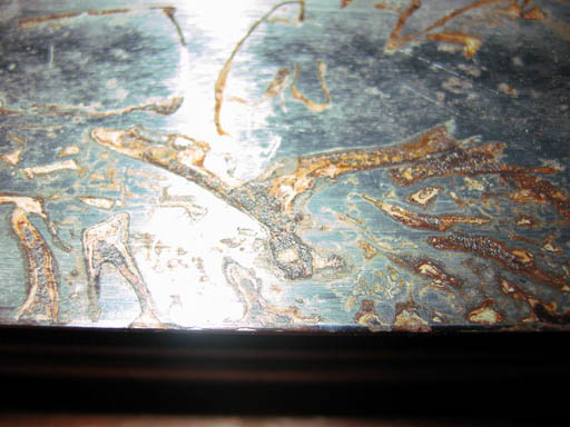
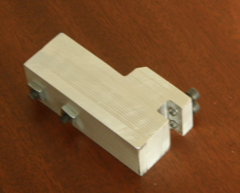
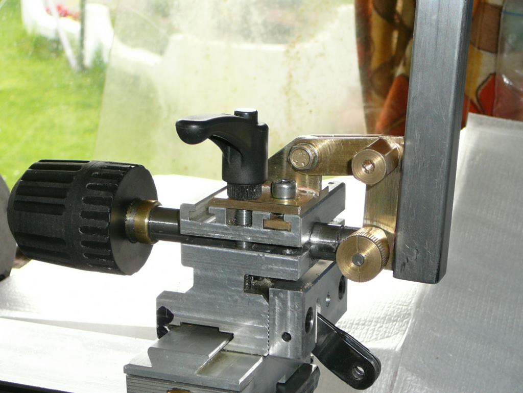
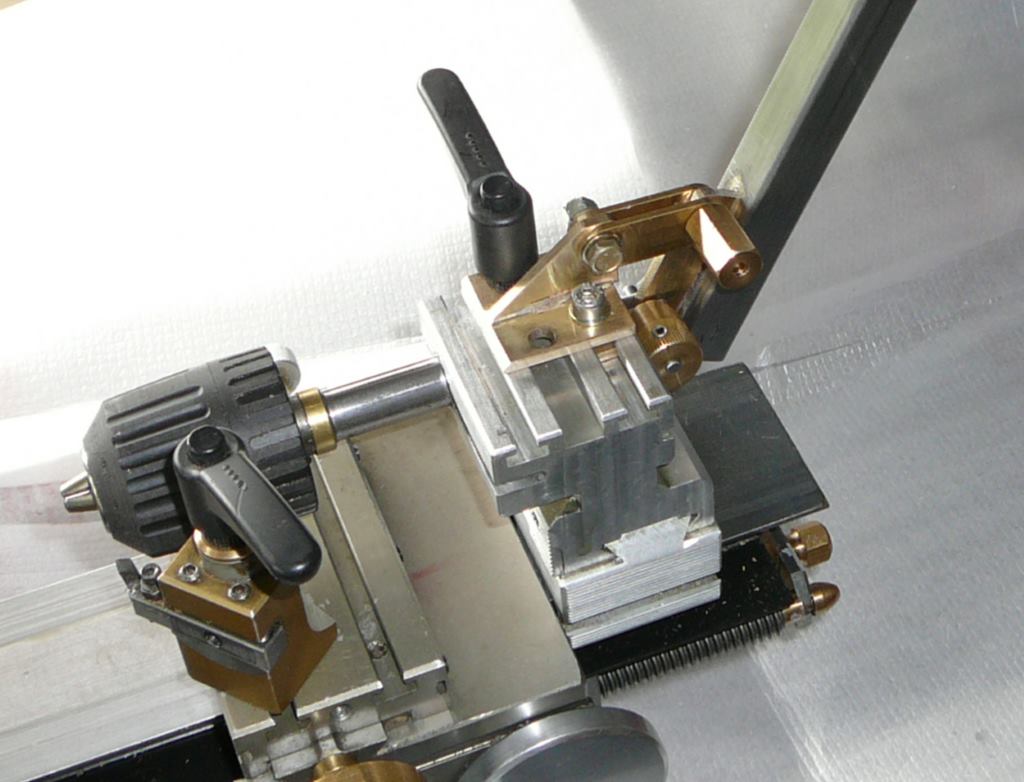
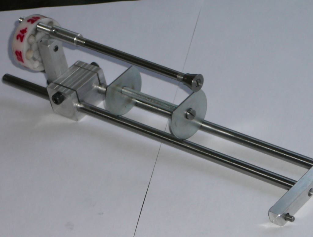
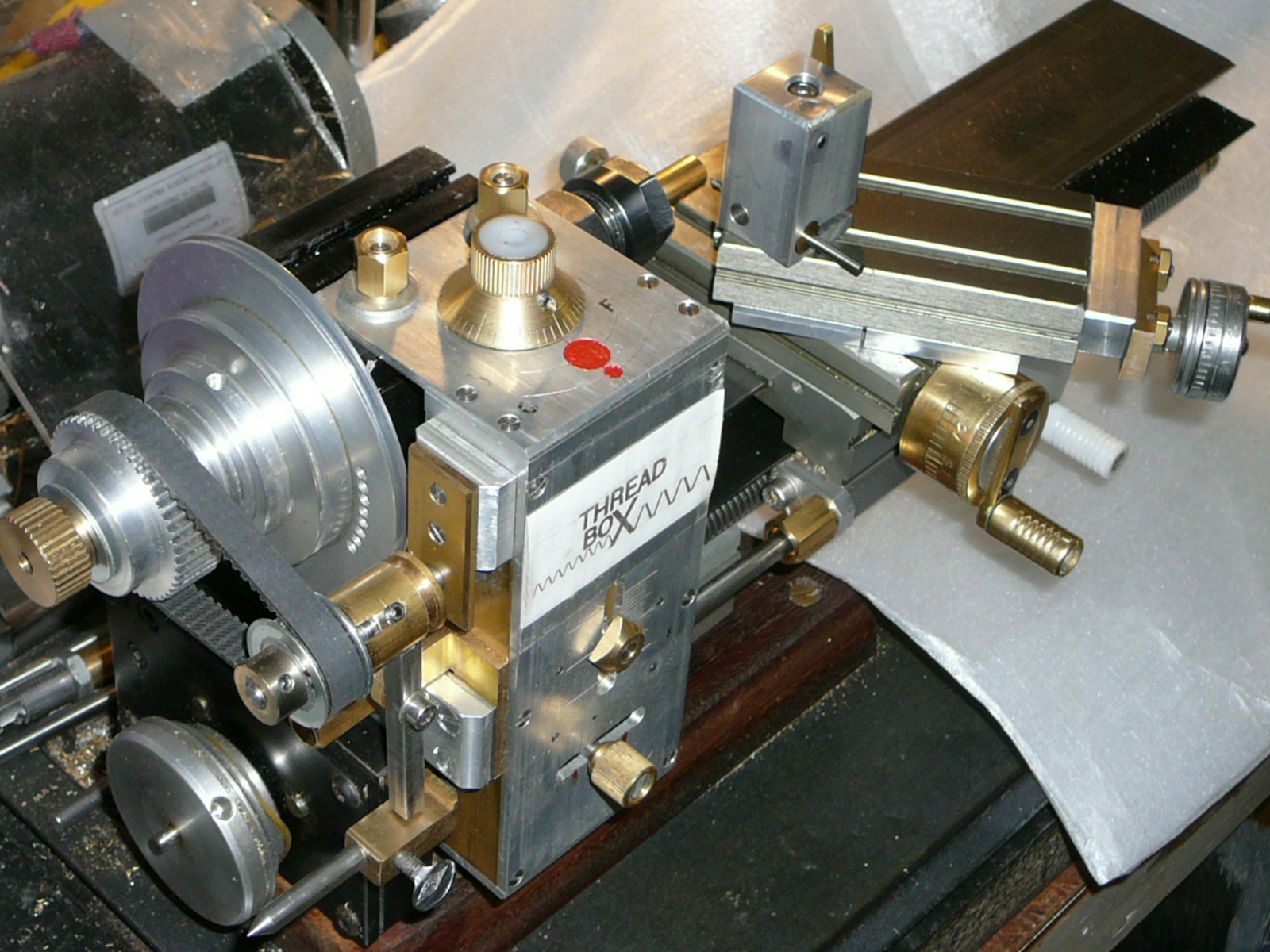
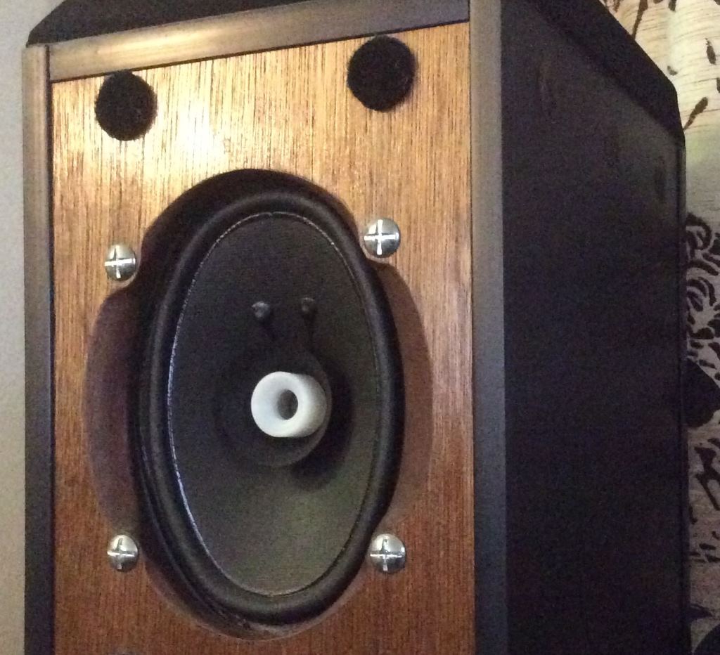