By Nick Carter
I have too many books. Books are stacked up everywhere in the house, and there are never enough shelves to hold them all. Taking stock of this situation I was faced with the need to build 4 bookshelf units (each one roughly 86" high and 20" wide with 8 shelves). I designed the bookcase to be made with plywood shelf boards fitted into dadoes (a fancy woodworking term for what we machinists intelligently call a "groove") in the sides of the bookcase. I decided to make a simple jig that would allow me to use a router for the dadoing operation. I think the methods of planning and construction will be of use for those in similar circumstances, who need to quickly make a jig or fixture in order to complete another project.
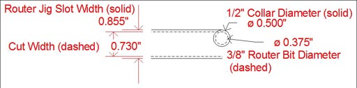
The router jig is a slot in a wide enough piece of material to support and slide the router base along, Destaco clamps are mounted to the underside for easy clamping to the plywood shelf uprights, and by integrating clamps into the jig I was avoiding the hassle of clamping the jig to the plywood with separate clamps for the routing operation. A standard guide bushing affixed to the router base runs against the sides of the slot. In this case the bushing I had on hand was ½" dia. ID and the router bit was 3/8" dia OD.
The width of the slot is the width of the desired dado (just over 23/32" or .719") plus the difference between the radius of the cutter and the radius of the guide collar (1/2"- 3/8"=1/8"), which equals .843". I wanted some clearance as the plywood I used was a little warped so I decided on a groove of .855 which would give me a dado width of .730". (Drawing 1) Distances in increments of .005 or .010 are easier to mill as you don't have to worry about those tiny little divisions on your micrometer dials and can just stick to the major divisions.
|
| Click the picture to download a dxf file. |
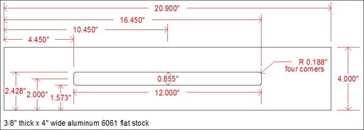
The length of the slot needed to be at least the width of the shelf (8.5") plus twice the diameter of the collar - with an eye towards using the jig in the future I made it just under the maximum travel of my Taig mill, 12". This length dimension isn't critical and neither is the slot's centering on the jig, what is critical is the width of the slot and if the outside edge is to be used as the lineup edge (to a pencil mark 2" from the actual dado centerline, for example) the distance from the edge of the jig to the slot edge. The drawing shows my final design (Drawing 2)
 |
| Click the picture to download a dxf file. |
The tolerances on the slot width and location from the wide edge are critical and should be kept to about +/- .001. The other features such as slot length and the distance from either edge have remarkably loose tolerances, on the order of +/- .250" (or more!). The tapped holes for mounting the clamps are dependent on the clamps used, in this case the diameter of the mounting holes is 5/16" and the screws I use are 1/4", so any hole can be off by 1/32" (half of the difference in hole size) and the clamp will still mount in the position initially selected. It would be difficult to not put a hole within 1/32" of a punch mark. Even if the clamp itself is off, the adjustable nature of the Destaco clamp means that I could conceivably be off of location by a wide margin with no ill effects on the utility of the jig.
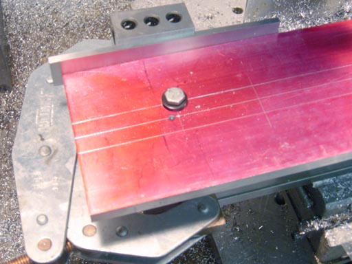
The first step after selecting the raw material (4" wide, 3/8" thick aluminum, 20.9" long which was the length of the piece I had in my material shelf) is to layout the slot. I sprayed the surface with red layout dye then scribed all the important lines (slot sides, center, and both slot ends) using a height gage. Notice my use of a large box parallel to support the stock at a right angle to the surface plate. You could use any good right angle, and if you don't have a setup like this you could just scribe the lines with a hermaphrodite caliper - just make sure the layout lines are either at or inside the required slot width.
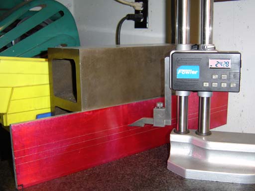 |
| I scribed all the important lines using a height gage. |
I drilled two holes (by eye, oversize, in an unused area) so that I could bolt the jig to themill table.
 |
| Jig bolted to the mill table |
Alignment of the jig was accomplished by clamping two 1-2-3 blocks to the rear of the table, with 1/8" parallels spacing the jig out so that it was aligned. You could indicate the length of the jig true, but it is much quicker to use this alignment method if your table is true on the back edge. The jig was raised off the surface of the table with 1-2-3 blocks as well.
 |
| Alignment of the jig |
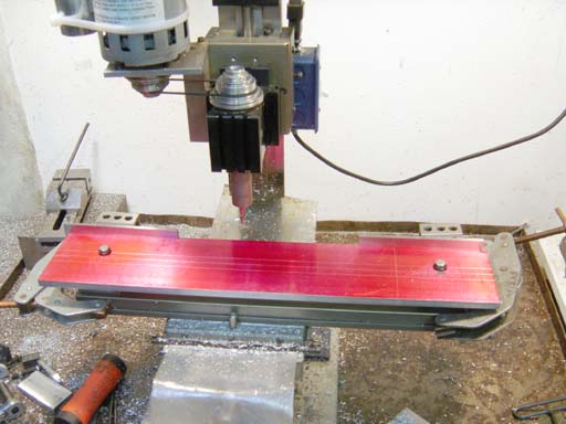
I selected a 3/8" three flute centercutting roughing endmill to rough the slot out, taking .125 deep cuts at a time, staying well within the layout lines. I roughed ugly and fast here, to quickly eliminate the bulk of the slot material. All deflection downwards will take place here, and not in the finishing cuts.
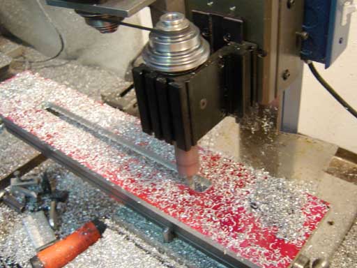 |
| Roughing out the slot. |
I then used an edge finder to find the jig edge, and finished the slot width with a 4-flute endmill ,using the the mill dials to make sure the slot was accurately centered to the width of the jig.
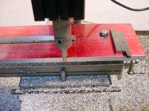 |
| Finding the jig edge. |
The length is not critical so I just kept to the layout lines. As I got close to the required slot dimension I used an adjustable parallel to gage the slot width. The adjustable parallel is one of the most under utilized gages in the shop and extremely handy for measuring straight sided slots, and more accurate than using your calipers due to the width of it's gaging surface. A DRO or CNC mill would of course make this whole process much faster and eliminate all these layout steps.
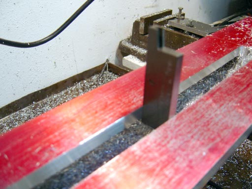 |
| Using an adjustable parallel to gage the slot width. |
Mounting the two Destaco clamps to the underside was quick and easy. The tolerances involved are very loose and the type of clamps you use dictates the location. I used a kant-twist c-clamp to affix the clamps to the jig, roughly lining them up with the scribed centerline. I then used a transfer punch to mark the holes for bolting the clamps to the jig.
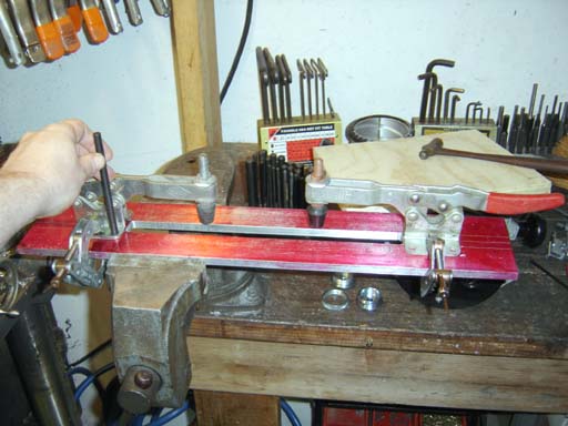 |
| Using a transfer punch to mark the holes for bolting the clamps to the jig |
The clamps were removed; holes were centerdrilled and then tap drilled on the drill press. I used a #1 drill for tapping a ¼"-20 hole with a form tap. Form taps cold form the threads rather than cutting, yield a stronger thread and do not need chip cleanup the way cut threads do. They require a larger hole than regular taps, the proper drill sizes are listed in Machinery's Handbook. The threads were tapped using a Tapmatic tapping head on my other drill press. It took me about as long as it takes you to read this paragraph. If I did not have a tapping head I would have chucked the tap in my cordless drill and carefully tapped under power, holding the jig in a bench vise. I often use that technique for work that is hard to mount on the drill press, or where I don't want to waste time changing the tap in my tapping head. I rarely ever hand tap anymore.
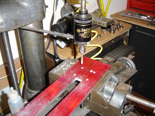 |
| Tapping the threads with a Tapmatic tapping head. |
Mounting the clamps by tapping holes in the jig was one option, I could have counterbored the jig for a nut, or countersunk it for a flat head screw, any method that keeps the top surface free of projections is fine. So why did I tap? There really wasn't enough material thickness for a ¼" nut counterbore, and countersinking for flat head screws takes almost as much time as tapping (under power), and would require using a wrench on both the screw above and the nut below, where tapped holes allow easier assembly from one surface (done under power as well, with a hex bit in my cordless drill). The clamps were mounted and the clamp spindles adjusted to give a strong pressure on the ¾" ply that I would be routing. The clamps can of course be adjusted for most thickness and widths of work making the jig versatile for the future.
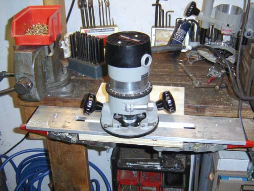 |
| Testing the attachment on a scrap piece of plywood |
I tested the attachment on a scrap piece of plywood and it worked perfectly, producing a good fit with the shelf in the dado. I did learn to make sure the router spindle was stopped (they take a long time to spin down) before removing from the jig as it is too easy to nick the side of the guide slot. I cut all the dadoes in the uprights with router "spin down" being the longest part of the operation. In the future I'll use a plunge base instead of a fixed base.
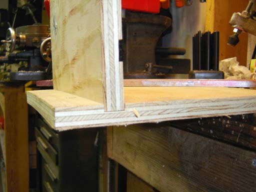 |
| The shelf fitted in the dado. |