Faking a Fourth Axis on the Taig CNC Mill
I am in a period of intense CAD/CAM study, learning the ropes of the BobCad/Cam program, as well as a few other programs, and studying general CAM principles to boot. The fruits of this will be a later article in the works entitled "Adventures in CAD/CAM". As a way of procrastinating I found myself diverted by BobCad/Cam's lesson on 4th axis programming. The Taig CNC mill I have is the 3 axis version, so I never gave 4th axis work much thought, although I was always intrigued by Tony Jeffree's use of his Y-axis motor attached to his homemade dividing head as laid out in his excellent article: "A Comprehensive Dividing Capability for the Taig (Peatol) Lathe and Mill"
Tony sort of glosses over the minutae of using the y-axis as a fake 4th axis, so I thought I would lay down the principles of my method and show some pictures of the results. The pictures I have are somewhat the same as Tony's - graduating a micrometer dial - one would think all we home shop machinists ever do is graduate dials! I will be using the technique for artistic ends soon, as it lends itself to engraving rings (I make jewelry for a living, besides my job as Taig-expert.) The applications are endless: cams, dials, discs, clock faces. In short, anything that needs a tool path wrapped around a circumference.
The first thing you will need is a dividing head or rotary table. I'm not going
to go much into that, but you have basically three options:
1) You can make a dividing head from scratch, making sure it has low backlash
in the gear train and will accept the nema 23 motor Taig uses.
2) Convert a small dividing head/rotary table to accept the nema 23 motor (same
caveat about backlash applies)
3) Buy a Sherline CNC ready rotary table.
I bought the Sherline table because I was able to get one at a good deal before they raised their prices last September. It uses a different coupling than the Taig uses, but all I had to do was remove the y-axis motor, remove the motor half of the CNC coupling, and attach the motor to the Sherline table. With practice it should take less than 5 minutes to switch between the axis. It helps to (read: You Must) have your rotary table/dividing head centered under the spindle in the y-axis, or you'll have to figure out some way of moving the y-axis by hand. Finally, lock the y-axis when the spindle is centered over the rotary table/dividing head. You will need to figure any backlash and change your y-axis backlash in your control program, make a note of the original value you had for the y-axis so you can go back painlessly.
Secondly you need to draw your part in CAD. Figure out the circumference of the round part you want to mill, using formula Circumference = Pi x Diameter. It isn't that crucial to have this to .001, as the conversion is not dependent, but you will get distortion of text, etc that use any moves around the axis if it isn't close. Make a rectangular box in your cad program that has the x-axis width and the y-axis as circumference. Draw your part in that box, with the lower left corner as 0,0 - make the box in another layer or blank it out while you are drawing the part, just make sure the box is there for the last step. Even if your milling does not go around a full circle, make this box. If you just want to mill a 45 degree arc, then keep your work in 1/8 of the box. You can convert angles to circumferential movement by using the formula: Circumference / 360 deg x desired angular movement. ( "/" means divided by)
Once the part is drawn, figure out the y-axis conversion ratio you will need.
It has two parts:
1) thousandths per full rotation of the y-axis motor, which in the case of the
Taig mill is .050"
2) Number of teeth in your dividing head/rotary table worm gear, which for the
Sherline table is 72 teeth
The ratio in my case is then 72 times .050", or 3.6" which is the
distance the y-axis will "move" to produce a full rotation of the
dividing head/rotary table.
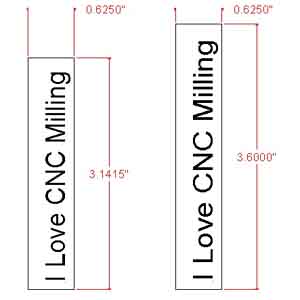
With the part in the box (it can hang over, just make sure the whole part and the box is selected) scale the drawing in the y axis only so that the total height of the box equals 3.6" in y. For example, if the diameter of my dial is 1", then the circumference (and the box you have drawn) is 3.1415" in the y axis. To scale this up or down to 3.6", in some CAD programs you just need to drag one end of the selection box (or enter in an absolute y-axis value) , but in BobCad I had to Cut it, then Paste it while entering a scale factor (and checking a box to only apply it to the y-axis). The scale factor would be 3.6"/3.14159" = 1.1459, for real precision you may want to do the math on a calculator if your CAD program isn't that precise.
If you haven't fallen asleep yet, what has happened is we have stretched/shrunk all the drawing elements only in the y axis, which distorts them on the screen, but when milled around the cylinder will appear as they did before the scaling is applied. remember we are converting inch movements to rotary movements, not inch to inch.
Now you need to use your CAM program to create the toolpath - try and make sure the axis moves in a direction that will not cause any chuck you have attached to unscrew. Also try and make the moves happen sequentially in the y-axis, just to save time of the table going round and round. In BobCad/Cam it was pretty quick to make an engraving toolpath that followed all the drawing elements. I selected the graduations first, then the numerals, all going in the same direction in the y axis....
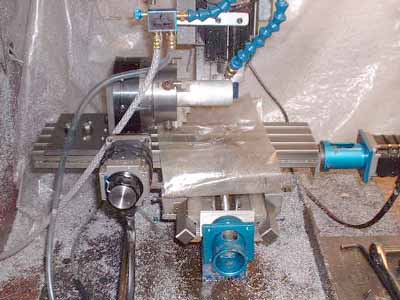
Here are the pictures of the actual fake 4th axis on my mill, and milling two dials (to be separated on the lathe and cleaned up)
|
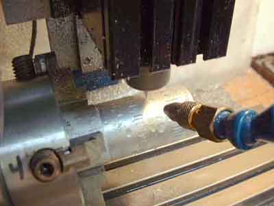
The Taig CNC Mill with the y-axis motor removed and mounted on the Sherline rotary table. The Sherline table is bolted to an angle plate so I can use it vertically. The Taig 4 jaw chuck is screwed to the Sherline chuck adapter (which comes with the Sherline table). |
|
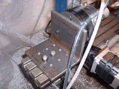
Details of the angle plate mounting. The angle plate is made from some HR steel angle which I machined square on my Atlas Shaper. I had to tap and drill for some mounting screws that allow the Sherline table to be fastened to the plate directly, instead of using clamps. The table is heavy, so try not to allow it to slam into your mill table! |
|
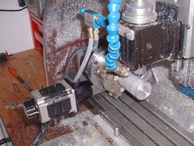
Milling begins with a vee engraving bit |
|
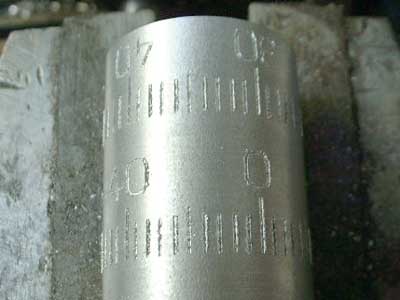
Engraving the graduations of the first dial. |
|
Engraving the numerals of the second dial. Notice that I could have used a very long bar and made a dozen dials all at once if I wished. The two dials are different in that the numberals are either up or down in relation to the graduations. |
|
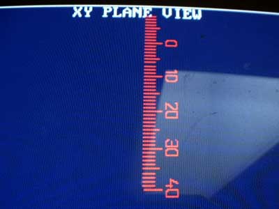
A shot of the MPS2000 screen showing that the mill thinks it is engraving in the y-axis. We sure fooled it! |
|
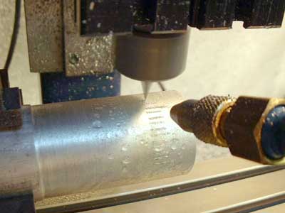
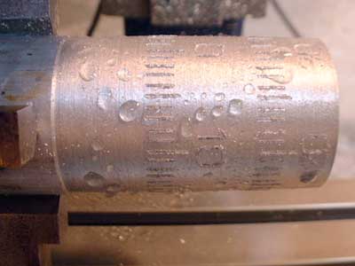
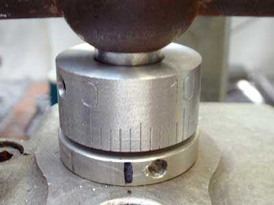
The finished dial covered in droplets of coolant |
|
I will part the two dials so that the graduations are on the edge of the dial. A wire brushing will clean up the burr on the somewhat gummy alloy of this piece of scrap Al bar . |
|
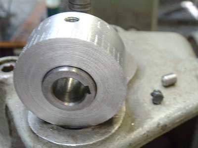
The finsihed dial, bushing, tapped for a setscrew - the little black plug is rubber that goes in between the screw and the bushing so the dial can rotate around but stays put under the pressure. |
|
The dial mounted on my Barker horizontal mill, which I converted from lever feed on the Z and Y axis to screw feed. The graduations show up better in real life than they do in the picture, but I could have anodized the dial blanks first, then engraved for a neater appearance, or I could fill the engraving with black ink. |
|
The scaling of a drawing, notice the original y axis length and the scaled length - hard to see, but the text is somewhat distorted in the y-direction. The x dimension is the same. This is easy to do in Autosketch, which I used to produce this drawing. You can notice the text seems thicker. It would be converted to polylines before or after the stretching, depending on your work habits. |
|
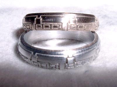
Here is an 18K gold ring, sitting on top of an aluminum test piece, which was engraved using the fake 4th axis. I generated the toolpath in Bobcad. The toolpath had to be curved as the ring was made of domed wire. I used TurboCNC to control the complex 3D motion needed to engrave the design. The ring is about .160" wide, with a 9/32" radius to the surface, and about .770" in diameter. This was the most complex job I have ever done. I was given the ring as it was and had to true up the surface while not losing too much of the gold! Just an example of what can be done (when you make the mistake of doing a friend a favor). |
Back to Nick Carter's Taig Lathe Page