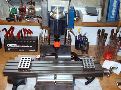
Assemble the column to the table with the wrench. Make it just tight enough to move by hand, but not so loose that it falls to the side (been there, left a nice gouge in my table the first time I did this).
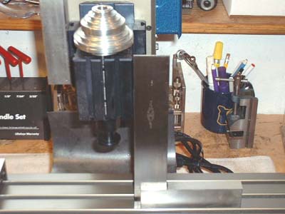
Place the square on the table and adjust the column so the headstock is square to the table.
Tighten it up and you can start using the mill.
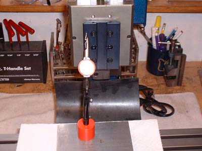
If you want more accuracy, use a dial test indicator to "sweep" the table. It is easier if you use blocks rather than running the tip into the table slots. You can drive yourself crazy trying to take out the last .001", so don't! But seriously, if you can get it perpendicular to within .001 over 8" that is pretty good for a milling machine. With practice you can get it under .001", but it takes some finesse.
Tighten the column, reindicate (might have shifted, I told you you could go insane). I find that tightening it as tight as possible with my hand choked up on the wrench so it is near the head is pretty good. Too loose and the column will shift, too tight and it will bend something (40 ft/lbs is too much! I did it and bent the front of the machine)
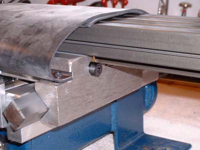
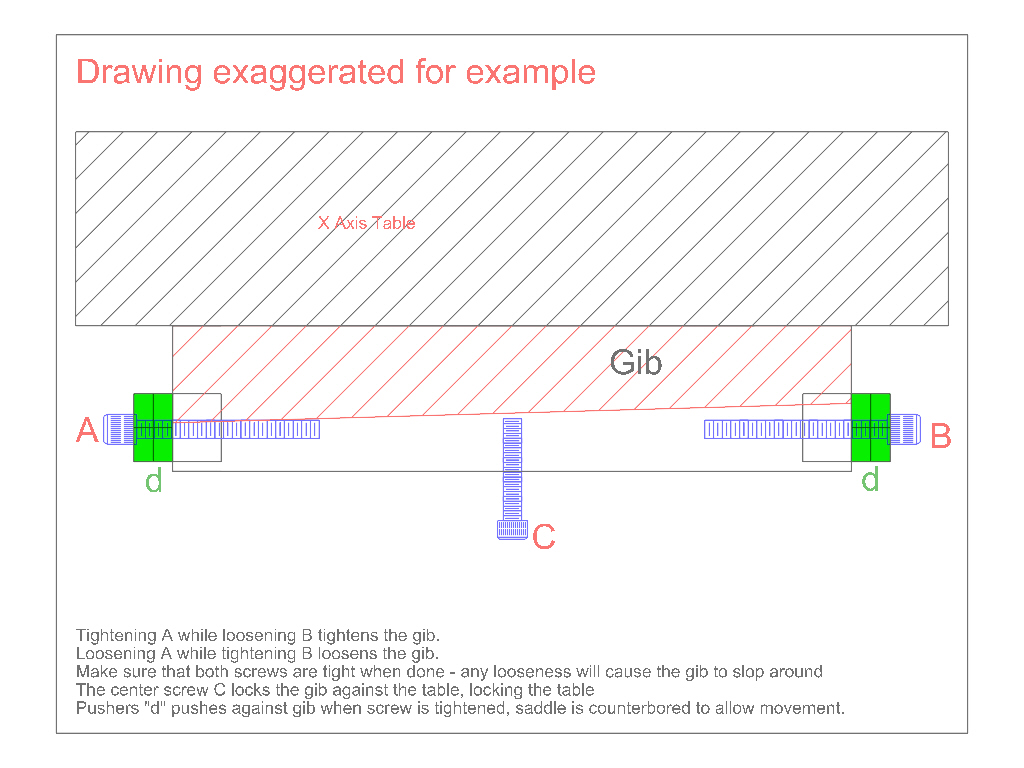
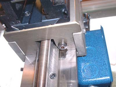
The right hand table gib adjustment screw.
Tighten the left screw inward while loosening the right screw out to tighten the table, to loosen the table tighten the right in while loosening the left out.
The screw in the middle of the front of the table locks it.
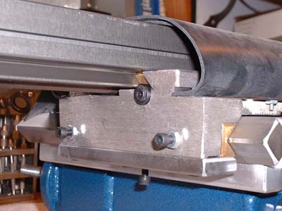
The left hand table gib adjustment screw. (top screw in picture)
The y-axis gib screws, adjust the two screws in or out to adjust the
gib. The bottom screw locks the table
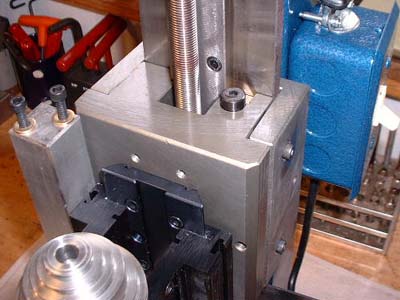
Sometimes the z-axis dovetail mount is out a tiny bit, which can through compounding of errors make the spindle not perpendicuar to the y-axis. Do not adjust it unless you know what you are doing! In practice I have found sometimes slipping a thin (.001) shim in the dovetail plate will correct this problem.
But again, don't do it unless you really know how to chase down errors! This can really drive you crazy sometimes. Not to mention driving me crazy when I try to fix your problem via email.