This article was born of two experiences. I recently made a small oscillating engine from a casting kit and the flywheel casting supplied with the kit was of a design that was boring to look at and did not match the style of the rest of the castings. The other was watching one of the many custom motorcycle reality TV shows, in which they had a guy making custom motorcycle wheels from aluminum on a large CNC machine. I thought to myself, why couldn't I do something similar on my bench top Taig CNC milling machine? So I did. This article is not about how to make exactly the same flywheel shown in this article, but some simple steps for producing a small flywheel on any of the CNC bench top milling machines that are available today.
Since I had the luxury of designing a flywheel for no particular engine, just as a fun "let's see if I can" prototype project, I decided on some simple parameters. The flywheel was to be produced from some 3/8" aluminum flat stock that was 4" wide, which I had in enough quantity in my scrap box that I could produce a couple if the principles were sound (or I could produce at least one if my initial ideas were flawed and I had to scrap a few).
I didn't want to get caught up in some complex CAM work so I decided that the design would be a 2-1/2 axis job consisting of simple pocketing and profiling to particular depths, and that after milling the flywheel I would clean up the bore for the shaft on the lathe rather then relying on tool changes while milling the wheel. I was also going to trepan (using an endmill) the blank out of solid stock and turn the OD on the lathe. In short the flywheel as it came from the mill would be treated just the same as a flywheel casting would ordinarily be machined.
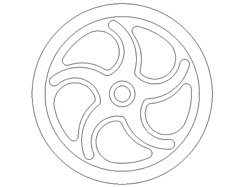
The drawing I produced in my CAD program (Autosketch) was a result of playing with various curves and lines, radially copying them around the flywheel until I had something that seemed pleasing to my eye. The main constraints were that no radius could be smaller than the endmill radius I was to use on the job, in this case a 3/16"diameter endmill. I chose that diameter because as a fun prototype project I wanted the milling time to be as short as possible. If one were to use a 1/8" or 1/16" endmill more detail could be included, and if one programmed some tool changes then the sky would be the limit.
|
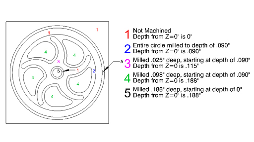
When the flywheel drawing was completed I imported it into my CAM program (BobCAD/CAM V18) and began the somewhat tedious work of selecting each drawing element, producing the tool paths from the geometry and generating the G-code for each element. The depths of each pocket group are shown in the drawing. One important factor in this process was that I was only milling one half of the total thickness of the flywheel. I first pocketed the overall relief between the rim of the flywheel and the boss around the bore. Then I milled the small relief design that went along the middle of the spokes. The holes between the spokes were pocketed to the full depth of 3/16" (half of 3/8") plus a small amount to allow for error. The bore was pocketed to be 5/16" undersize by about .010". The last step was a profiling pass around the periphery of the wheel to separate it from the stock.
 |
Once the CAM work was finished on one half I then reloaded my drawing in the CAM program and mirrored the design around the y-axis, producing the other side of the flywheel. I repeated all the pocketing and profiling and saved it in a separate file. I now had two G-code files, "flytop.cnc" and "flybot.cnc". In hindsight I would give them even less confusing names such as "firstside" and "secondside" as I had a moment of panic in the middle of machining where I couldn't remember which file was for which side.
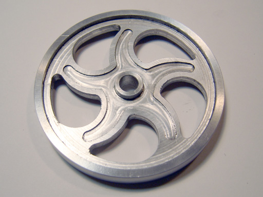
I ran the "simulate" function in BobCAD/CAM and found that it drew something that looked like the flywheel I had originally conceived. If you look at the finished flywheel you will notice that the grooves in the spokes do not go as far towards the edge as on the drawing, for some reason BobCAD/CAM truncated the toolpath, probably because the radius was exactly the radius of the endmill - in the future I'll add about .005 to the width in hopes of avoiding this truncation. You could certainly hand code a flywheel without a CAM program but with the many inexpensive 2-1/2 axis CAM programs available there really is no reason to suffer through that tedium.
The machine I use is the Taig 2026 CNC milling machine with the stock Taig controller (Bilevel Chopper Drive) using TurboCNC V4 in DOS as the control program. The g-code program for each side is 613 lines long. I used a 2-flute 3/16" diameter endmill, held in a collet, and the spindle speed was set to 10,000 rpm.
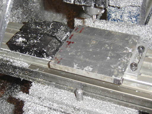
I decided to use a fixture plate on the mill table to hold the blank for the flywheel, clamping the workpiece between a rigid bar set square to the milling machine table, and two edge clamps. I could have fixtured it just as well in a vise, but I wanted to make sure I could mill as much of the stock as possible without running into a hardened jaw or parallel. The drawing shows the layout for milling both the top and bottom halves of the flywheel. The workpiece should have a machined square edge that rests against the rigid bar and the other edge that gets picked up by the edge finder should also be reasonably clean.
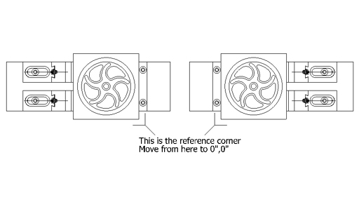 |
I put the edge clamps on the right of the blank and the bar on the left and
clamped it down tight. Using an edgefinder I found the lower left edges and
zeroed the axis. I then moved x and y-axis 2" and re-zeroed so the 0,0
position was in the center of the blank. I inserted a 3/16" endmill in
the collet, jogged the z-axis down and zeroed when the endmill just kissed the
workpiece surface. As an afterthought I marked the lower left edge with an indelible
marker pen, and as an after-afterthought I filed a small notch in case I erased
the pen marks with the coolant. I loaded the g-code for the top surface to the
control program, did a dry run (always do a dry run or verify cycle in case
there is an unseen error in your program), turned the spindle and the mist unit
on and ran the program.
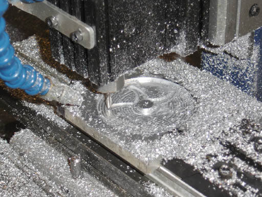
The machining was uneventful; my intermittent misting unit kept the work cool
and free of chips and the first surface was machined in about 12 minutes. The
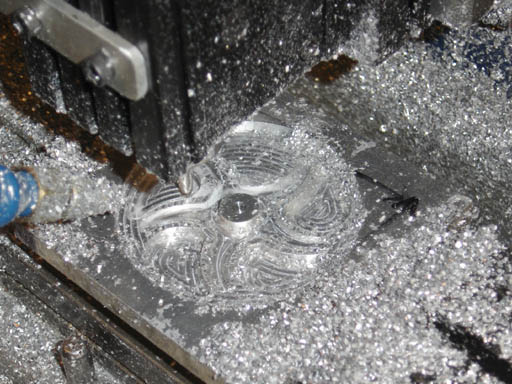
Pictures show (picture01) (feature 2 in drawing 2), machining the spoke grooves
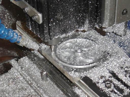
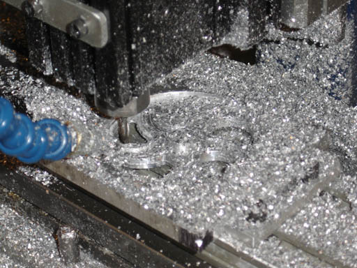
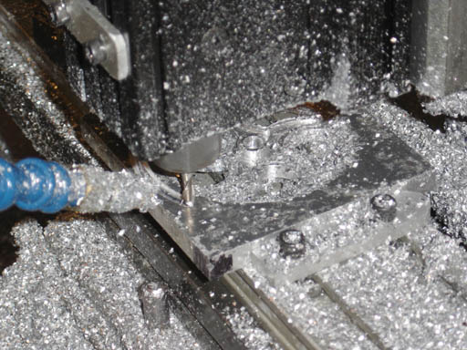
(picture02) (feature 3 in drawing 2), the machining of the spoke holes (picture
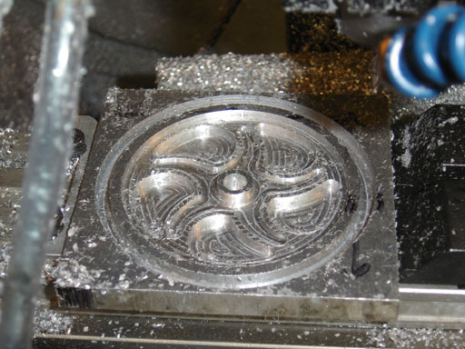
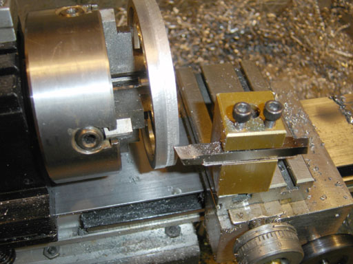
03) (feature 4 in drawing 2), and the trepanning cut around the flywheel (picture04)(feature
5 in drawing 2)
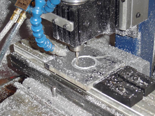 |
| The start of the machining, feature 2 |
 |
| Machining the spoke grooves, feature 3 |
 |
| The machining of the spoke holes, feature 4 |
 |
| The trepanning cut around the flywheel, feature 5 |
The next step was to remove the work, clean off the chips and burrs protruding from the surface, and remove the edge clamps. The blank workpiece now looked like a pulley had sunken into it. The clamps were replaced on the left side of the bar and the work flipped over on its y-axis so that the filed notch was now on the lower right hand side. I loaded in the g-code program for the bottom half ("flybot.cnc"), zeroed the x and y-axis, this time to the right hand lower corner, then moved 2" to the left for the x-axis and up again for the y-axis. In theory I was now at the same 0,0 location as I was for the top half.
 |
| "The blank workpiece now looked like a pulley had sunken into it." |
 |
| "The work flipped over on its y-axis." |
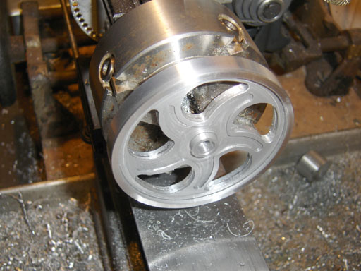
I began the machining and had a small moment of self-doubt as I waited for the
program to start milling the spaces between the spokes. When that operation
started I was gratified to find that the spaces now went clear through the flywheel
and that I had located the edges correctly and kept everything square. The machining
continued until the profile cycle finished it's last pass and the flywheel came
free of it's surrounding material. If I had used a vise it would have dropped
down, but as the groove was 3/16" wide the endmill just kicked it to the
side. Be careful when machining a part using this technique, sometimes it will
jam against the cutter and it will always put a small ding in the side of the
work, but in this case I was going to turn the OD so it didn't matter.
 |
| "The spaces now went clear through the flywheel." |
 |
| "The machining continued until the profile cycle finished it's last pass." |
The flywheel, although rough on the periphery and bore and needing copious deburring, looked just like I had imagined it. I mounted the flywheel on my Taig lathe, drilled and reamed the ID to 5/16" and turned the OD. I polished up the rim and removed the flywheel. I then spent some time deburring all the edges.
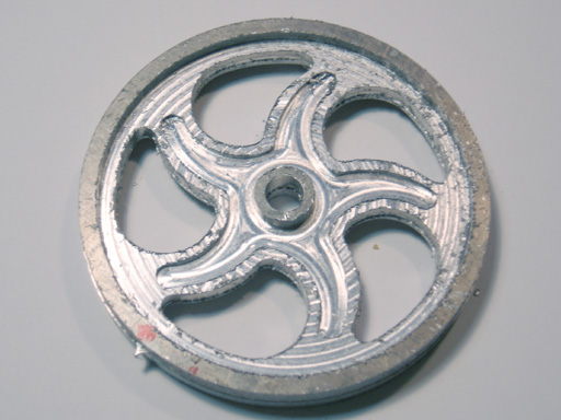 |
| "Although rough on the periphery and bore and needing copious deburring, looked just like I had imagined it." |
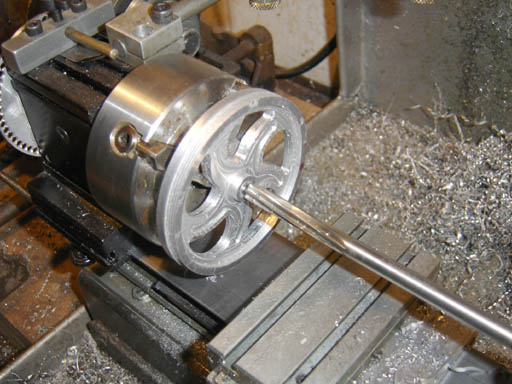 |
| "I mounted the flywheel on my Taig lathe, drilled and reamed..." |
 |
| "...turned the OD..." |
 |
| "I polished up the rim..." |
The finished flywheel looked as good as any I had machined from a casting.
 |
This prototype flywheel showed me that it was certainly possible to produce an interesting and aesthetically pleasing flywheel on my CNC mill, and that with some more time spent on design and machining I could produce almost any design I imagined. This strategy of milling half of the design, mirroring the drawing, milling the other side, trepanning and turning to final size could be used not only on flywheels but on small wheels for R/C cars, train wheels and drivers, or machine hand wheels. The project shows that while a simple flywheel like this would be difficult to produce manually, CNC can reduce the complexity and allow the unfettered design of beautiful small parts.