
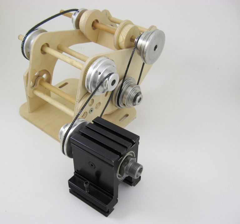
Fig. 6.1: New Low-Speed Drive Prototype
Here is an example of the time and effort that can be sacrificed to tunnel vision. All the time my 12-speed drive was chugging along, running through my mind was the idea that someday I’d redesign it to be efficient, compact and elegant. Finally, the time arrived and Fig. 6.1 shows one of several wood mock-ups of a prototype design to be made of aluminum and realize my dream.
The most important functional objective was to overcome the belt slip at low speeds. If 3M pulleys were to be used, they should be mounted on the motor and countershaft where the higher speed would keep them in their best power range. The countershaft/jackshaft and jackshaft/spindle speed reduction would use belts that could handle more power. But what belt to use at those low speeds?
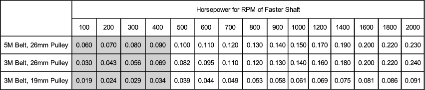
Fig. 6.2: 3M - 5M Belt Performance Comparison
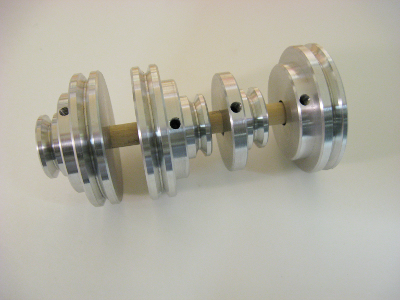
Fig. 6.3: 5M Pulley Set
The table in Fig. 6.2 adds more data from Gates to show that the lower the speed, the greater the superiority of the 5M over 3M pulleys and belts. Again, the shaded area contains my extrapolations. At small pulley sizes, a 2L belt is no better than the 5M and 3L or 4L belts won’t work at all. A no-brainer. I chose the 5M format. I even went so far as to make the 2-step 5M pulleys shown in Fig. 6.3 that would have been required to implement it. But that’s about the only useful thing I achieved. There were other problems; lack of a suitable small motor, belt tensioning headaches and just plain old fatigue over a long, frustrating series of disappointing models. Eventually I gave up, threw off my nineteenth century Luddite ways and entered the brave new world of variable speed DC motors.