
I figured that, if a better solution existed, I’d have better luck finding it if I knew more about how PMDC motors actually behaved. Appendix B - DC Motor Characteristics draws on various notes I made to research this topic and gives the rationale for my selection. Basically, this is simply “higher power at lower no-load speed”.
The 5M pulley set provides a ratio of 26/50 = 52% or 50/26 = 192%. So if the motor would run down to, say, 180 rpm the pulleys would drop that to about 93 rpm. If 180 rpm is 10% of the no-load speed, the motor should be rated at 1800 rpm. The high-speed range would then give about 3450 rpm. 1/4 hp at 1800 rpm should be plenty. The range of 93 to 3450 rpm looks pretty suitable for a lathe. If it were a 90 volt DC motor, I could use the same Dart 125D controller.
A friend had exactly the motor I needed, an Indiana General model 3430D-69 producing .4 hp at 1800 rpm, 3.0 amps at 90 vdc. He had bought it at surplus some years ago but, natuarally, I couldn’t find one anywhere. The closest I could get was a Bodine Model 4037 that worked out not too differently.
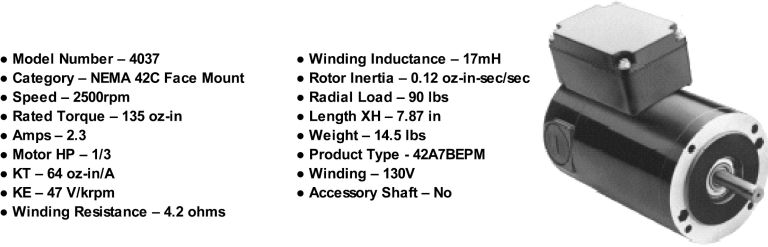
Here are the motor specifications from Bodine’s web site:
The one I bought was brand-new surplus but without the mounted controller box. Dart’s service people told me that the 125D would really put out about 100 volts and would run this motor just fine, albeit a little slower; i.e. 100/130 x 2500 = 1923 rpm. The maximum power would also be reduced proportionately; i.e. 100/130 x 1/3 = .256 hp. All-in-all not a bad fit to my criteria. Since I wanted to keep the GS for my mill, I actually bought another Dart controller and Hammond case for this installation.
This motor weighs 14.5 pounds and I wasn’t comfortable hanging it from the headstock. Since I already had a sub-base for the lathe, attaching the motor mounting post to it retains the illusion of an integrated unit without the risk of headstock deformation. Fig. 8.1 shows how it looks on the Taig.
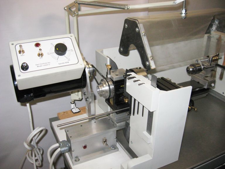
Fig. 8.1: Bodine and Dart on Taig
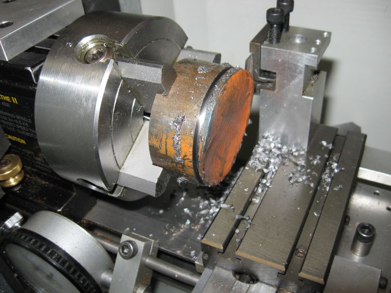
Fig. 8.2: Bodine Parting Operation
This system does everything the GS did plus offer very good low-speed power. Fig. 8.2 shows a parting operation on a 2 inch diameter piece of 12L14 using a 1/16 inch HSS parting tool at just about 150 spindle rpm. I timed this and estimate feed at a little less than 1 inch per minute. Any more than this will slip the belt.
Perhaps somebody will successfully apply more power to a Taig but it won’t be me. I’m not sure the machine would take much more anyway. But my odyssey is over and I’m happy to be free of the compulsive preoccupation with pushing the envelope.