By Tom Benedict
Photos by Author
One of the advantages of having a CNC mill or lathe in the shop is that you can run it unattended while you are doing other things. One of the disadvantages is that without some way to apply coolant to the tool, the only other thing you will be doing is applying coolant yourself.
There are a number of flood and mist coolant units on the market so I won't go into the hows and whys of setting them up. But to really take advantage of any of them you need some way for your computer to tell the coolant when to be on and when to be off. Most CNC controllers already understand the RS274 commands for controlling coolant but in order to use them you need one more piece of hardware: You need a relay box.
When deciding whether to take on this project, keep in mind that relay boxes are not limited to controlling coolant. Depending on the software you are using, a relay box can also be set up to control a spindle, to run a tool changer, a clamping fixture, a bar puller, or to accomplish any number of other tasks. The possibilities are limited only by your imagination.
Commercial relay boxes are available for small CNC mills and lathes, but they start around $175 and only go up from there. My mill controller can drive two relays so I decided to build a box with two relay-controlled outlets, one for coolant and one for the spindle.
You can build an inexpensive relay box provided you are willing to do some circuit design and wiring. A slightly more expensive relay box can be built with no additional circuitry and very little wiring. Being lazy by nature and leery of my own wiring I opted for the second choice.
A number of manufacturers make solid state relays that can be triggered by a TTL signal and switch up to 240V at 25A or more. The ones I chose are Crydom D2425 relays, but similar devices are made by other manufacturers as well. Most suppliers carry these for about $30 apiece, but I got mine off Ebay for $3 each. They are overkill for the application, but at the Ebay price they were tough to beat
Aside from the relays the other component that requires thought is the enclosure. Because solid state relays can generate a lot of heat you will need an enclosure that can act as a heat sink. Also, the enclosure should not have any holes that would allow metal chips to get in and short out the electronics. For this project I used a 1590C enclosure from Hammond Manufacturing. Bud Industries makes an almost identical enclosure, the Econobox CU-234. They are roughly 4.7 x 3.7 x 2.0 inches. There is nothing magic about this size and any number of other perfectly suitable enclosures would also work as long as all of the components can be made to fit.
In addition to the enclosure and relays you will need at least one electrical outlet, a fuse holder, a power cord, and some way to get the digital signals from your computer to the box. The outlet and power cord can be found at the local hardware store. For digital signal wires I used CAT5 network cable, also available from any number of local sources.
If you are planning to drive two sockets off of one relay, the outlet can be used as-is. Since I set up two sockets controlled from two separate relays, a little modification was required.
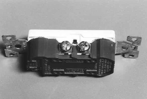
Photo 1 shows an overview of the hot side of the outlet I used for this project.
Photo 2 is a close-up of the screw terminals for the hot side of the outlet. Between the two terminals is a small tab. This tab can be broken, which allows each socket to be powered separately.
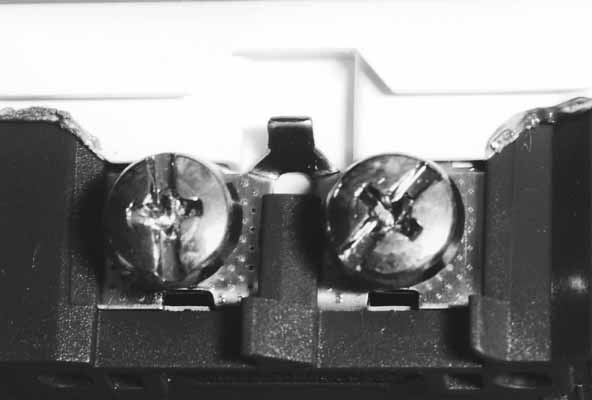
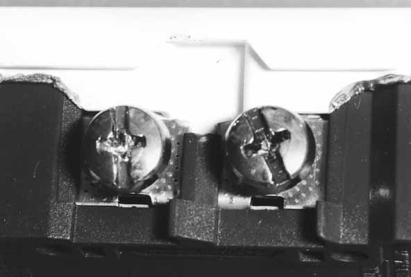
Photo 3 shows the outlet after modification. It is important that this modification be done on the hot side of the outlet. The neutral side of the outlet should be left as-is.
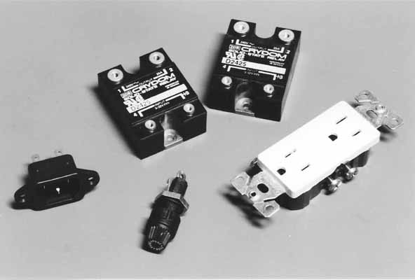
Before doing any wiring, arrange all of the electrical components and plan how to fasten them in place. The components I used are shown in Photo 4.
Most electronics manufacturers have CAD drawings of their components on their web sites. This simplifies component and mounting hole placement. The cutouts needed for each of the components are shown in Figure 5. If you wind up using other components be sure to check if drawings already exist for them.

Photo 6 shows the enclosure with the cutouts and mounting holes drilled.
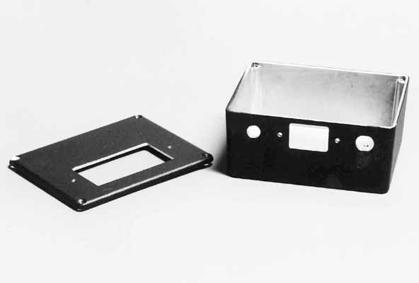
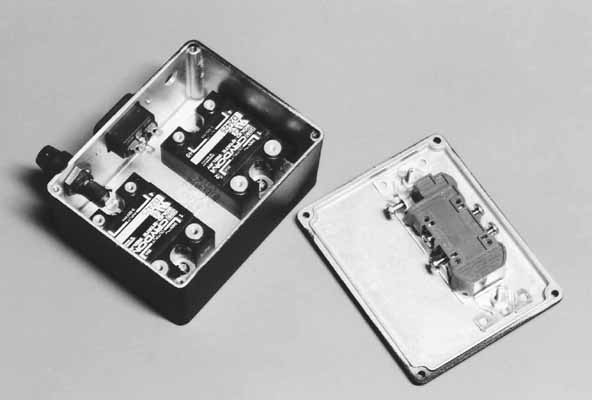
Photo 7 shows the enclosure with all the components mounted. When mounting the solid state relays, try to get as much thermal contact as you can between the relays and the enclosure. I used heat sink compound when mounting mine.
The next step is to cable everything up. The wiring diagram for the relay box is shown in Figure 8.

When building a circuit of this sort, it is always a good idea to have some sort of electrical isolation between the high voltage lines and the signal lines coming from the computer. The relays I used have opto-isolation built in to them, so no additional circuitry is required.
When it came to making the wires for the box I took a tip from the people who build combat robots: Build it so it's hard for things to fall apart. Every wire has a ring terminal crimped and soldered onto each end. Every joint is covered with heat shrink tubing. This may be overkill, but there is almost no risk of a wire coming loose. 14 gauge stranded copper wire was used throughout.
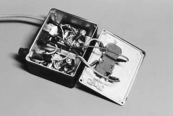
The CAT5 network cable I used for the digital signal wires has four twisted pairs. Using twisted pair wiring reduces electrical noise. Each pair of wires can be used for a separate relay, so I used only two of the four pairs. Again, I used crimped and soldered ring terminals on the ends of the digital signal wires. The Crydom relays use different screw sizes for the power lugs and the signal lugs. Power lugs use #8 screws and signal lugs use #6. Careful choice of ring terminals for the digital wires and the power wires makes it difficult to cable up the relays incorrectly. The final wiring job can be seen in Photo 9.
Each of the relay drivers in my controller has a ground pin and a signal pin, and can source +5V at 125mA. This is plenty to switch the Crydom relays. I connected my controller's ground pin to the negative side of the relay and the signal pin to the positive side of the relay, as in Figure 10. When the signal pin goes high, the relay will turn on.
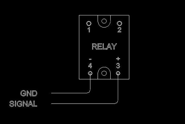
The same sort of scheme can be used if you wire the relays directly to a parallel port. The negative side of the relay goes to a ground pin on the parallel port and the positive side goes to the pin on the parallel port you are using to control the relay. When the signal pin on the parallel port goes high, the relay will turn on.
My initial design for this relay box did not include a fuse. Luckily, before I built anything I had the opportunity to speak to an electrician and to several other people with experience in things electrical. All of them convinced me of the importance of using a fuse. The fuse in the relay box serves two purposes: The first is to limit the current that can go through the relays. The relays I used are rated for 25A, so I used a fuse with a lower rating. The idea here is to have the fuse blow before the relay. The second purpose of the fuse is to protect the circuit in case of a short. I like to think that the precautions I took in wiring up the box would make it so a short can never happen, but life rarely turns out that way. I added the fuse.
In selecting a fuse for your relay box be sure to choose one with a high enough current rating for your spindle motor and coolant system. When an AC motor starts it draws considerably more current than it does during normal operation. The exact number varies depending on motor type but a safe figure is five to seven times the normal operating current. My spindle draws 0.8A during normal operation. I used a 10A slow-blow fuse, which should be more than enough for the motor, but still offer protection against a direct short.
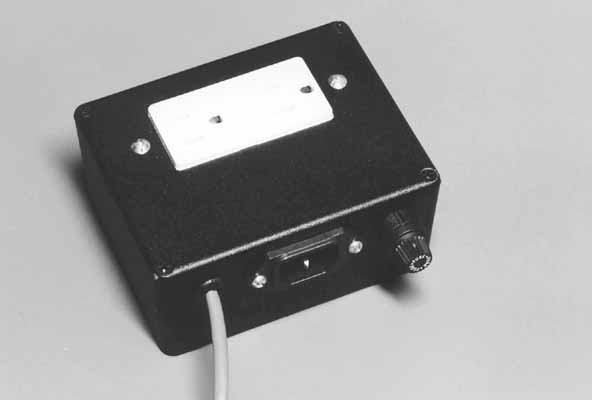
At this point the relay box can be closed up and put into service. As you close the box be sure there are no loose or exposed wires that might short out. When first plugging it in be ready to unplug it in a hurry in case there are any problems. My completed relay box can be seen in Photo 11.
Even after building the relay box I left the normal power switch on my spindle motor. In case I need an emergency spindle stop or need to change a tool, I can still manually turn off the spindle at the switch.
After the relay box is installed your software will still need to be configured to use it. Since this depends entirely on the software you are running, your best bet is to consult the manual that came with your software.
Once your software is configured to use the relay box you can begin controlling your spindle and coolant from inside your part programs. Depending on how many relays you built into your relay box, some or all of the following RS274 commands should work:
M03 Turns the spindle on clockwise
M05 Turns off the spindle
M07 Turns coolant A on (typically set up as a flood coolant)
M08 Turns coolant B on (typically set up as a mist coolant)
M09 Turns all coolant off
Since I have a box with two relays I can use M03, M05, M07, and M09. When writing a part program, I put an M03 and M07 at the beginning to turn on the spindle and coolant. At the end of the program once the part has been made, I put an M09 and M05 to turn off the coolant and the spindle.
Now that I have a relay box on my CNC mill I am finding more and more places where one could be used. It only took a couple of hours to build and cost far less than a commercial unit. If you choose to build one, I hope you are as pleased with your results as I am with mine.
Digi-Key Corporation
800-344-4539
Mouser Electronics
800-346-6873
Newark
800-463-9275
1ea 110V AC Electrical Outlet
2ea Crydom D2425 Solid State Relay (or equivalent)
1ea AC Power Receptacle
1ea AC Panel Mount Fuse Holder
1ea Power Cord
4ea 20 Gauge #6 Ring Terminals
8ea 14 Gauge #8 Ring Terminals
2-5' CAT5 Network Cable
2'ea 14 Gauge Stranded Copper Wire in Three Colors: White, Black, Green
Various screws for mounting components
Heat Shrink Tubing