Most of us reach a point in our projects where we have to make use of gears. Gears can be bought ready-made, they can be milled using a special cutter and for those lucky enough to have access to a gear hobber, hobbed to perfect form. Sometimes though we don't have the money for the milling cutters or gears, or in search of a project for our own edification seek to produce gears without the aid of them. This article will explain how to draw an involute gear using a graphical method in your CAD program that involves very little math, and a few ways of applying it to the manufacture of gears in your workshop.
The method I describe will allow you to graphically generate a very close approximation of the involute, to any precision you desire, using a simple 2D CAD program and very little math. I don't want to run though familiar territory so I would refer you to the Machinery's Handbook's chapter on gears and gearing which contains all the basic information and nomenclature of the involute gear which you will need for this exercise. Some higher end CAD programs already have functions for generating the involute tooth from input parameters, but where's the fun in that?
When we talk about gears, most of us are talking about the involute gear. An involute is best imagined by thinking of a spool of string. Tie the end of the string to a pen, start with the pen against the edge of the spool and unwind the string, keeping it taut. The pen will draw the involute of that circle of the spool. Each tooth of an involute gear has the profile of that curve as generated from the base circle of the gear to the outside diameter of the gear.
|
The easiest way to teach is to demonstrate, so here are our parameters for drawing a:
16 Diametral Pitch (P), 20 Tooth (N), 14-1/2 Pressure Angle (PA) involute spur gear
For our method we need to compute the following as well:
Note: Click on any drawing to download a .dxf file of that drawing.
| Open up your CAD program and draw concentric circles of the Pitch Diameter (D), Base Circle diameter (DB), Outside Diameter (DO), and Root Diameter (DR). Add a circle of .25" diameter for the bore of the gear. Make sure the circle centers are at x=0, y=0. | 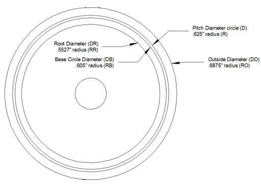 |
|
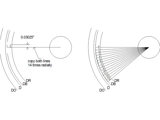
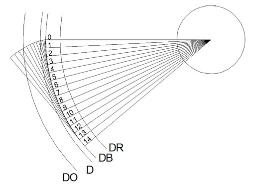
1) Draw a line from the circle center (0,0) to the base circle perpendicular to your grid. In other words at 0, 90, 180 or 270 degrees. I chose 270 degrees. 2) Draw a line 1/20th of the Base Circle Radius (RB) long (FCB = .03025") at a right angle from the end of that line. This line is now tangent to the base circle. It will be very hard to see unless you zoom in on the intersection of the base circle and the lines. 3) Radially copy the two lines (center at 0,0), make 14 copies at 2.86 degrees apart (ACB), for a total of 15 line pairs. Depending on the diameter of the gear you may need more or less lines, smaller gears need more, larger gears may need a smaller fraction of RB (base circle radius). 4) Number each set of lines, starting with 0 for the first one, going to 14 Drawing shows the two lines, and the copies of the line laid out and numbered. |
 |
|
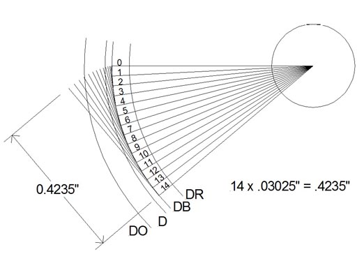
5) Extend the tangent line for each copy so it's length is the 1/20th of the base circle radius (FCB) times the number that you have next to that tangent line (0 x FCB, 1 x FCB, 2 x FCB…14 x FCB) extend them from the tangent point. Most CAD programs will make this very easy, providing that you started the line from tangent point, usually you just change the length parameter for each line, in Autosketch there is a display showing the line data and retyping the length extends the line from its start point. Make sure you zoom in on the drawing so you extend the correct line. Drawing shows the tangent lines extended, and the length of tangent #14, which is .4235" or FCB x 14 |
 |
|
6) Starting at tangent line #0, draw a line from the end of tangent #0 to then end of tangent #1, from the end of tangent #1 to tangent #2, tangent #2 to tangent #3 and so on. You should now have a very close approximation of the involute curve starting at the base circle and extending past the addendum circle. Trim the involute curve to DO, the outside diameter of the gear. Drawing shows the involute drawn along the ends of the tangent lines. |
 |
|
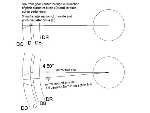
7) Erase all the tangent lines, leaving the involute curve generated by the process. Make a line that goes from the intersection of the involute curve and the pitch diameter circle (D) to the center of the gear. Note that this will not be the same as the line going from the start of the involute at the base circle (DB) to the center. 8) Draw a second line ¼ of the Gear tooth spacing (GT) radially from the first line; usually this is best accomplished by radially copying the line from the first. 4.5 degrees is ¼ of the gear tooth spacing (GT=18 degrees). 9) Now mirror a copy of the involute curve around this second line, make sure you leave the original curve, thus copying the other side of the involute 9 degrees (1/2 GT) from the pitch circle (D) intersection with the involute. Drawing shows steps 7 - 9 |
 |
| 10) Erase the radial lines, leaving the two involute curves. Draw a line from the start of each involute at the base circle to the center of the gear. Trim those lines to the Root Diameter (DR) circle. | 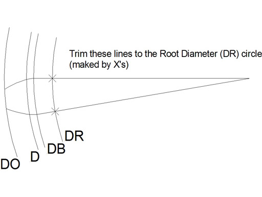 |
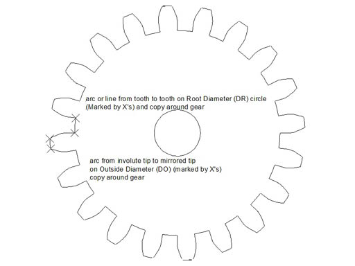
| 11) Erase all the circles except the Root Diameter (DR) circle. Draw a
curve from the outside tip of one involute to the other, which has a center
at 0,0 (the center of the gear) thus drawing the outside of the tooth (the
curve has the radius of RO). You now have a completed gear tooth.
12) Radially copy the completed gear tooth 19 times around the Root Diameter (DR) circle, spacing the copies 18 degrees apart (GT), making 20 gear teeth (T) in total. 13) Erase the Root Diameter (DR) circle and make a curve (or straight line) between ends of two teeth which has a center at 0,0 (the center of the gear). Purists will note that I have omitted the small fillet generally drawn at the bottom of the root. I did not draw it because I will be milling this gear on my CNC milling machine and the endmill will provide a fillet automatically. 14) Radially copy that curve or line around the gear as you did with the gear teeth. You now have a completed involute gear. |
 |
Milling a gear from flat stock with CNC If we want to mill this gear out of a flat plate on a CNC milling machine we need to figure out what diameter endmill will generate a minimum radius that won't interfere with the gear. If you are lucky enough to have access to a laser or water abrasive jet machine then you don't have to worry about this. We can do this graphically by drawing two meshing gears and either inserting a circle of the diameter of an endmill in the tooth gullet - it should be apparent whether it interferes with the gear teeth (remember that we are concerned with the fillet the endmill produces, not the endmill itself, it can overlap the other gear's tooth), or by inquiring in the cad program to the length of the root arc. In this case a 1/16" endmill will not interfere with the gear teeth meshing.
A rule of thumb that seems to work is to use an endmill with a diameter not
larger than: DR * Pi / 2T = 1.1054 * PI / 40 = .0868"
A 1/16" endmill is .0625" so it should work, I have not tested this rule of
thumb for all possible gears so revert to graphical analysis if you have any
doubts. The drawing is imported into a CAM program and the g-code generated
to mill the gear profile.
| Picture shows the gear being milled | 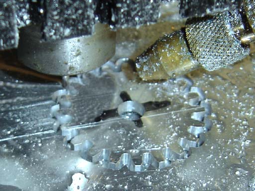 |
| Picture shows the two completed gears meshing with a distance between centers of D (the sum of the pitch radii of the two gears). | 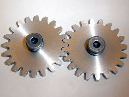 |
The gears milled with the method seem almost perfect and mesh perfectly in spite of the small steps that make up the approximate involute.
In his excellent article on "Spur Gears and Pinions" (HSM April 1999, Vol. 12, #2 pp. 8-15), John A. Cooper outlines a method for forming a gear with a cutting tool that is a circular rack of the same pitch as the gear. Part of his method entails cutting the individual teeth, then lowering the cutter by half the circular pitch (CP) while keeping it engaged with the blank, thus rotating the blank while keeping the teeth in mesh and taking a second series of cuts, generating a good approximation of the involute.
Using what we have learned through drawing the gear allows us to expand on the procedure and shows the relation between the rotation of the gear and the movement of the rack like cutter. On the lathe you make a cutter out of tool steel that is a circular rack of the same pitch as the gear, for the gear in the previous exercise the rack has 14.5 degree sides, the same as an acme thread, so grind a tool bit the same for as for an acme thread. The grooves are pi/P (CP) apart, or 3.1415/16 (CP=.1963"), cutting flutes are milled and the cutter hardened. You then make a gear blank of the desired size (same as the drawing example, DO = 1.375") and mount it on a dividing head, chuck the cutter you have made in the mill, and bring it down so the middle of the cutter is aligned with the midpoint on the gear. Take a cut(s) to the full tooth depth, across the width of the blank. Rotate the blank 1/8th of the gear tooth spacing (GT/8, 18 deg./8, 2.25 degrees), rather than leaving the gear in mesh with the cutter. Move the cutter in the direction of rotation by 1/8 x CP (1/8 * pi/P, .0245") Take another cut to full depth, repeat the process until you have made eight passes. Retract the cutter against the direction of rotation by pi/P (.1963") and begin the process again until all the teeth are cut.
| Drawing shows the movement of the rack cutter and the gear blank for each 1/8th CP movement of the rack, and each 1/8 GT rotation of the blank | 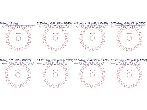 |
| Drawing shows the movement of the cutter against the gear relative to the gear blank and how it is generating the involute form. | 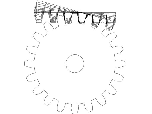 |
| Drawing shows the cutter and the gear. | 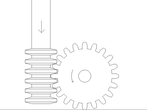 |
While this method is tedious (unless you have a CNC milling machine and 4th axis) if you do eight passes, you can certainly get away with two or four passes and make a perfectly serviceable gear. It does lend itself particularly to making worm gears of almost perfect form.
You actually don't need to draw the gear for this method, but after drawing the gear you will have a better understanding of how the method works, and how far the blank needs to be rotated and the cutter moved.
Another use of this method: Printed paper patterns (on label stock, particularly) could be used to grind single point form tools for use in a fly cutter or on your shaper, for sawing wooden gears by hand with a jewelers saw or plasma cutting large gears from steel plate.
I'm sure the crafty reader will find many other uses for this technique. This method can also be used with traditional drafting techniques, pencil and paper, but it will take a much longer time. The original example of this method was taken from "Analysis and Design of Mechanisms" for drafting one tooth and copying each tooth as you rotate a tracing around the circle.
I love manual drafting but there are so many inexpensive and free CAD programs available now that it would be a good time to upgrade if you are still using dividers and a t-square.
For those of you with a love of mathematics and computer programming there is another way of generating the involute curve using polar coordinates, which lends itself to the generation of the curve in various programming languages or with spreadsheet and CAD macros. A quick search on the Internet using the term "Polar Involute" will return many pages dealing with that method.
If you are making meshing gears that have a large ratio (say a 10 tooth gear and a 48 tooth gear) and you draw them in mesh (separated between centers by half the pitch diameter of each gear), you will notice that the larger gear undercuts the teeth of the smaller gear, thus producing interference. There are strategies for dealing with this such as increasing the center distance (thus backlash), stubbing the larger gear's teeth, undercutting the smaller gear's teeth, etc, some further research on your part will allow you to deal with this problem should it occur.
I hope this leaves you with a better understanding of the geometry of an involute curve and a practical method of drawing gears for your projects.
Copyright Nicholas Carter, 2007
Back to cartertools.com