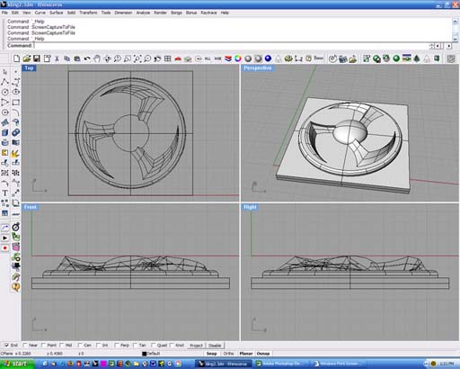
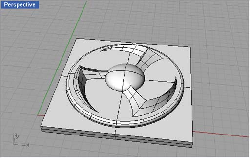
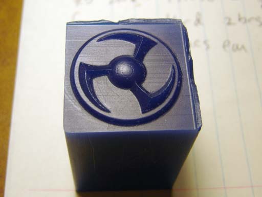
A 1.125" x 1.125" x .1875" part designed in Rhino. No, it's not anything but a fun little design. One of the jokes that my wife and I have are that if the whole machine sales business ever evaporates I'll start a business called "Nick's Knobs". Thus it could be a knob, or an escutcheon, an earring, or other piece of jewelry, heck it could be a set of spinning rims for when you "pimp your ride", assuming your ride is a skateboard.. The parts that will be milled are only .125" deep. The bottom left corner of the part is at 0,0,-.1875
In order to produce a 3D design you need a CAD program that allows 3D work. I love Rhino, but there are a number of programs available ranging in price from inexpensive to mortgage-inducing. I have a number of CNC Links (CAD, CAM and CNC control) on my main page.

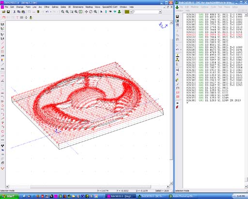
I imported the part into BobCad V20 (which accepts Rhino format files) The roughing toolpath is then generated in Bobcad, specifying the diameter and radius of the endmill used (1/16" dia, 1/32" radius, or "ball-end mill". The "stepover" is .030" and the depth per layer is .030" or roughly half the diameter of the endmill (.0625"). This is largely material dependent.
The red lines show the path the endmill tip will take across the work each time it moves down incrementally from the surface of the material (it took 7 steps) to the surface of the part. The roughing toolpath has 13196 lines of g-code.
You can use any CAM program that will accept a 3D model or file (usually one or more of .dxf/.dwg, .iges,.stl, as well as Rhino's native format .3dm) Again there are many links on my main page.
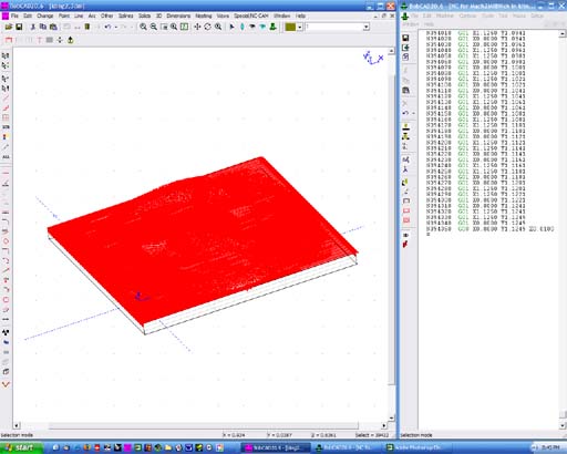
The finish toolpath, yes it looks like a solid block of red! For finishing the tool starts at the surface of the part and steps over .002" at a time. If I wanted an ever smoother finish I could have had it step .001" or even .0005" but that would increase the filesize and milling time proportionally. The finish toolpath has 39436 lines of g-code.
It is not unusual for people doing fine work (jewelry, medical, aerospace, etc) to use a tool with a diameter of .010 or .005" and a stepover of almost microscopic proportions...such programs can take a day or more to run....
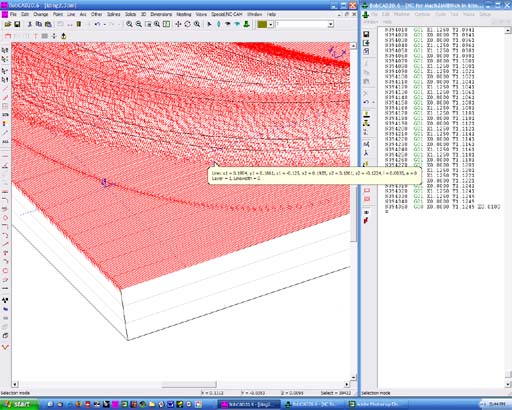
A closeup of the finish toolpath showing the little lines. Here's a little
sample of what the code looks like:
...
N410 G01 X0.0000 Y0.0341
N420 G01 X0.0000 Y0.0361
N430 G01 X0.5176 Y0.0361
N440 G01 X0.5345 Y0.0361 Z-0.1208
N450 G01 X0.5614 Y0.0361 Z-0.1190
N460 G01 X0.5634 Y0.0361
N470 G01 X0.5874 Y0.0361 Z-0.1205
N480 G01 X0.5923 Y0.0361 Z-0.1212
N490 G01 X0.6056 Y0.0361 Z-0.1246
N500 G01 X0.6081 Y0.0361 Z-0.1250
N510 G01 X1.1250 Y0.0361
N520 G01 X1.1250 Y0.0381
N530 G01 X0.6266 Y0.0381
N540 G01 X0.6176 Y0.0381 Z-0.1212
N550 G01 X0.6036 Y0.0381 Z-0.1185
N560 G01 X0.5891 Y0.0381 Z-0.1164
...
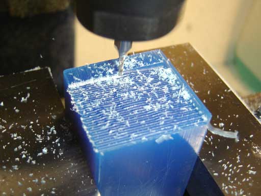
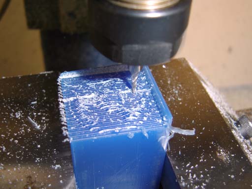
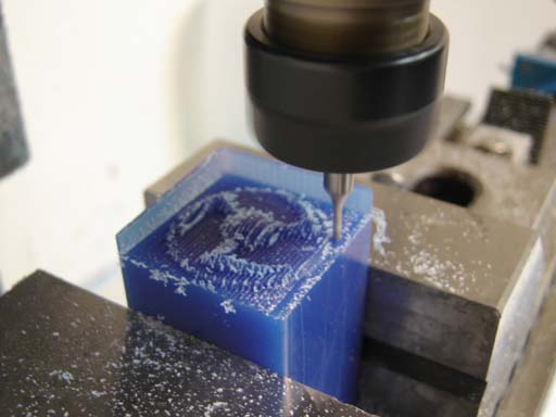
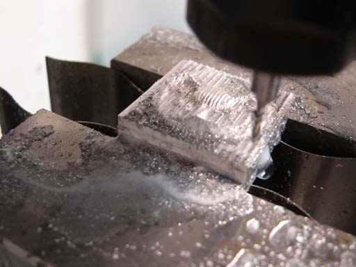
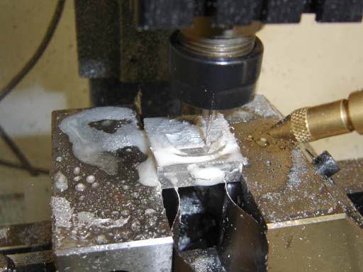
Roughing the design in a piece of jewelers wax, used both for proofing CNC programs (it machines freely and is forgiving of errors) and for investment casting fine jewelry.
The roughing runtime was about 1/2 hour, back and forth, back and forth. Time to drink some coffee.
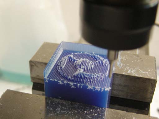
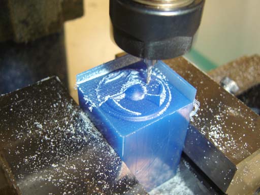
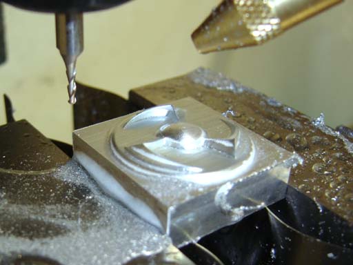
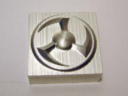
Those fine striations are more akin to grinding marks, each one being a segment of a 1/16" diameter circle with a chord of .002" length... you do the math. Notice the radius left on the internal corners. I could then make a final toolpath using a different tool and cut around the circle and profile to make it sharp cornered, but not at the interface of the arms and the sphere...that would require yet another tool with a sharp "V" tip, and another set of toolpaths. You get the idea...
I hope that this explains the basics of 3D part generation on a CNC milling machine, let me know if you would like anything clarified...