Page 2 - Back to Page 1
|
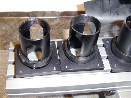
The CNC stepper motor mounts. |
|
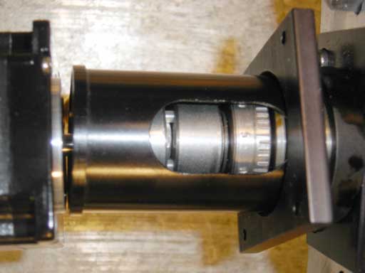
The tube threads onto the bearing block, and the collar clamps it once adjustement is completed. |
|
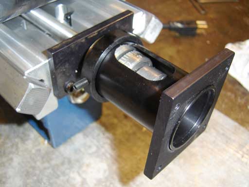
The mount completed. |
|
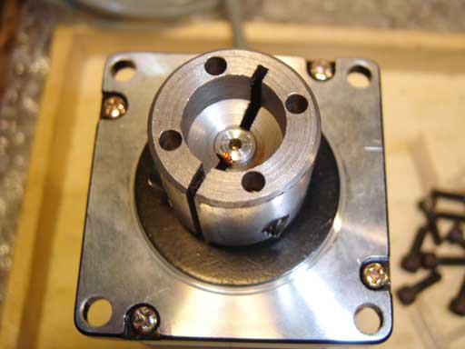
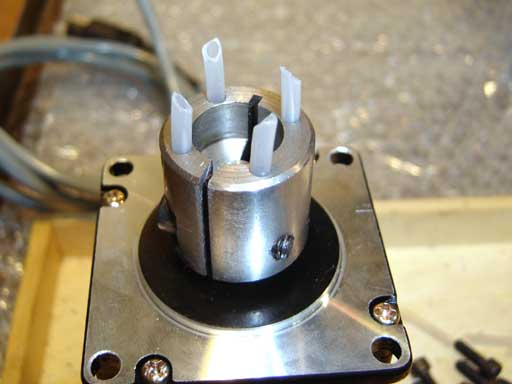
The stepper motor coupling half. The stepper shaft should be just at the bottom of the bore. The side screw clamps it tight. |
|
The coupling tubes inserted in the coupling half. One user found that trimming them to diminishing lengths made assembly easier. I asked the factory why tubing instead of solid rod and they said they found that solid rod would shear more easily under the stresses than tubing. |
|
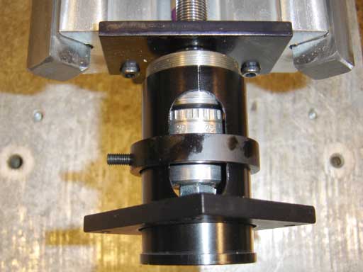
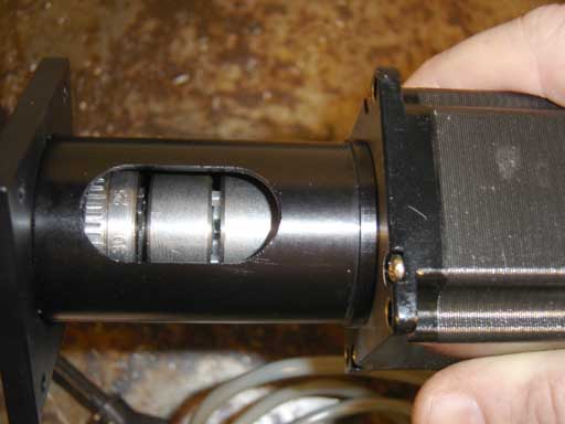
Inserting the tubes into the screw coupler half. This can take some wiggling and might drive you crazy. Turn the coupler half while rocking the motor around and you'll get it. |
|
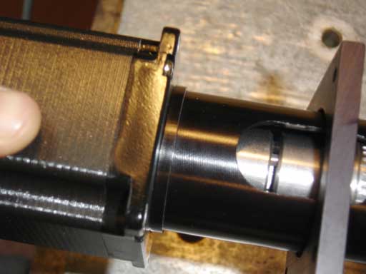
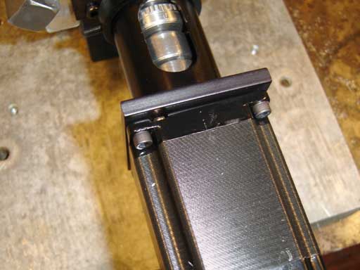
The gap is adjusted to be 1/8"-1/16" and the motor butts against the tube end. |
|
Another view. |
|
The motor is fastened to the plate. Make sure that the motor doesn't "cock" when the screws are tightened. |
|
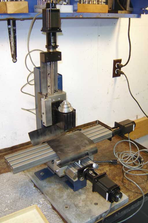
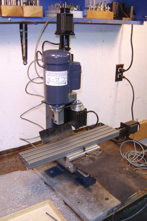
Basic assembly of the CNC mill completed. |
|
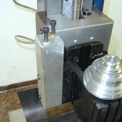
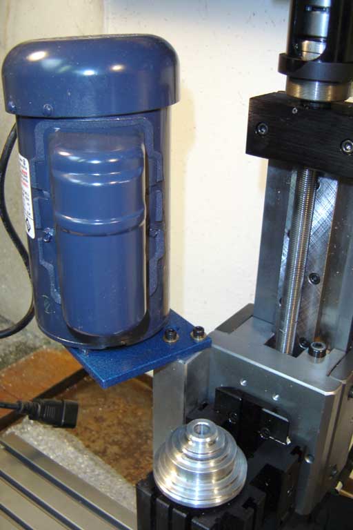
The motor mount attached to the headstock. |
|
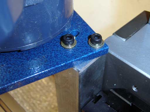
The motor mount plate attached with the two screws. |
|
The motor, mounted. |
|
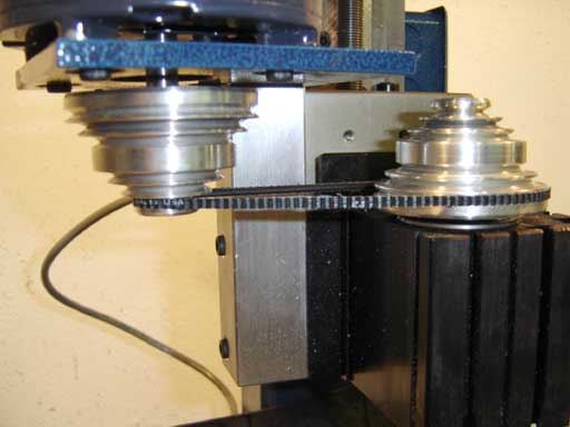
The pulleys should be aligned so that the motor and headstock shafts are parallel and the pulleys are in the same plane. The belt will suffer if care isn't taken with alignment. The motor can be adjusted up and down and for twist by moving the motor mount in the headstock slot. Be careful as it is heavy. if the belt makes a clicking noise then you need to adjust the alignment. |
|
The motor assembled. When running the mill for the first few times you will notice that it has a hard time coming up to speed on the fastest pulley setting. After time the grease will thin and everything will start fine, but at first run it in the next to highest groove until the headstock warms up. |
|
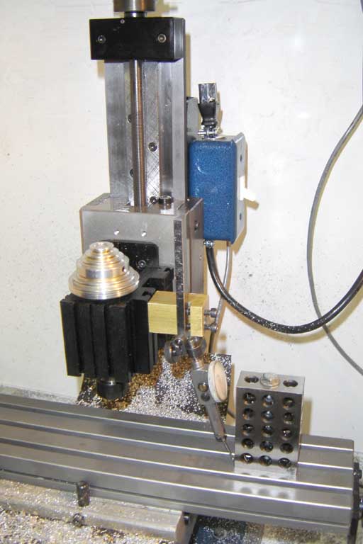
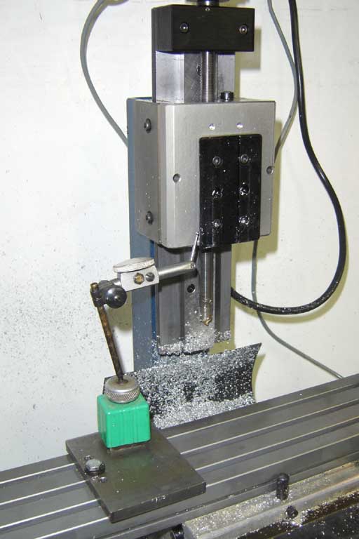
This is somewhat advanced, determining if the slide travel is perpendicular to the table by running the inidcator up and down a square (1-2-3 block) on the table, and adjusting the column by tapping with a soft hammer while the mounting nut is slightly loose. |
|
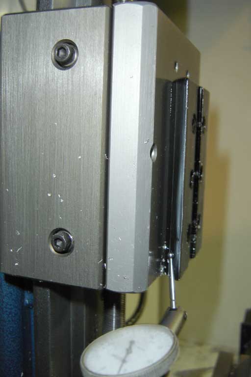
Once the z-axis slide is determined to run perpendicular to the table, you can check that the dovetail headstock mount in parallel to the travel of the slide by running the tip of an indicator along the dovetail. Slack all the dovetail mounting screws, but leave one slightly tight and adjust again by tapping with a soft hammer to bring into alignment. This can really make you crazy. But it will allow the greatest accuracy. But really, don't try this until you are comfortable adjusting things... |
|
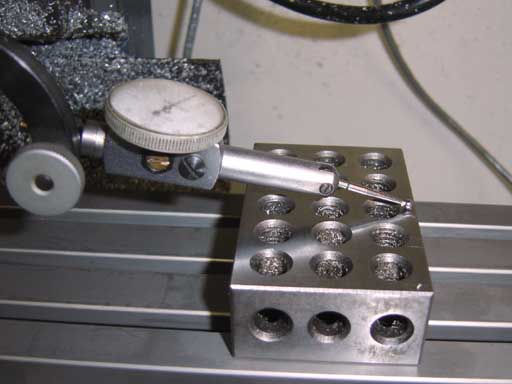
Closeup of the indicator tip against the dovetail. See below about Cosine error.... |
|
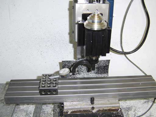
Once all that fiddling is done, test to see how well you have it aligned by sweeping the table. |
|
If you can get it to within .001 over 8"-12" you can call yourself an expert. I use the same block rather than two because I don't have a matched pair... |
|
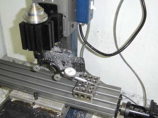
You want the tip of the indicator to be roughly parallel to the work surface to be gaged. You can read all about Cosine error here...if you don't have enough to think about already. |